
Car Alarm Simulator

The car alarm simulator circuit operates by utilizing the voltage produced by the vehicle's alternator. When the car engine is running, the alternator generates a higher voltage, typically around 13.8 to 14.4 volts, compared to the resting voltage of approximately 12 volts when the engine is off. This voltage difference can be harnessed to activate an LED, providing a visual indication of the car's operational status.
The core components of the circuit include a voltage comparator, an LED, and resistors for current limiting. The voltage comparator is configured to compare the voltage levels from the vehicle's battery and alternator. When the engine is off, the comparator detects a lower voltage and keeps the LED turned off. Conversely, when the engine is started, the increased voltage from the alternator triggers the comparator, which then allows current to flow through the LED, illuminating it to signal that the car is running.
In terms of construction, the circuit can be built on a breadboard or a printed circuit board (PCB) for a more permanent solution. The LED should be chosen based on the desired brightness and visibility, while the resistors must be calculated to ensure that the LED receives the appropriate current without exceeding its maximum ratings. Additional features, such as a buzzer or additional LEDs for different statuses, can be incorporated for enhanced functionality.
Overall, this car alarm simulator circuit serves as a useful tool for vehicle owners to easily monitor their car's engine status, providing both educational and practical applications in automotive electronics.This is a car alarm simulator which using the LED as a simulation output. This simple circuit can tell you whether your car is running or not by detecting the voltage difference when the car is on and off. This occurs because when your car This is a car alarm simulator which using the LED as a simulation output.
This simple circuit can tel l you whether your car is running or not by detecting the voltage difference when the car is on and off. This occurs because when your car is running the Alternator puts a out a voltage a little bit higher than when the car is off.
This circuit actually is a kits, you can get the kits at But it is very possible to you to build your own car alarm simulator circuit. 🔗 External reference
Related Circuits
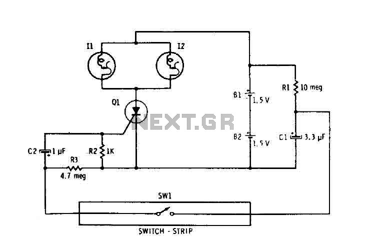
Capacitor C1 is connected continuously through a supply of 3 volts to a 10 megohm resistor R1. The capacitor charges relatively slowly to 3 volts. When switch SW1 is closed, it connects the charged capacitor C1 in series with...

False alarms caused by semiconductor failures are eliminated with this burglar alarm circuit, which is equipped with relays. Additionally, the circuit is nearly immune to false triggering. With a standby current of less than 0.1 mA, it incorporates all...
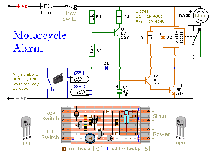
The circuit board and switches must be protected from the elements. Dampness or condensation will cause malfunction. Without its terminal blocks, the board is small. Ideally, you should try to find a siren with enough spare space inside to...
This circuit employs the widely used and easily accessible LM3914 integrated circuit (IC). The LM3914 is straightforward to operate, does not require external voltage regulators due to its built-in voltage regulation, and can be powered by a variety of...
These devices are low-cost, high-speed, dual JFET input operational amplifiers featuring an internally trimmed input offset voltage (utilizing BI-FET II technology). They require low supply current while maintaining a large gain-bandwidth product and fast slew rate. Additionally, well-matched high-voltage...

The plumbing and fuel system installations are complete, and final checks on the electrical system are currently in progress. The bike loom is being tidied up and tested. There is a query regarding two unused connectors in the 2003...