
CAR STOP LIGHT

In this circuit configuration, capacitor C1 serves as an energy storage element, initially charged to 3 volts through the resistor R1. The high resistance value of R1 (10 megohms) ensures that the charging process is gradual, allowing the circuit to stabilize before activation. Once the switch SW1 is closed, the stored energy in C1 is rapidly transferred to capacitor C2 and resistor R2, creating a series circuit that facilitates the charging of C2.
As C2 charges, it reaches a threshold voltage that is sufficient to trigger the gate of the silicon-controlled rectifier (SCR). The SCR acts as a switch that allows current to flow through the parallel-connected bulbs I1 and I2, causing them to flash. This flashing action is a result of the SCR turning on and off in response to the charge and discharge cycles of the capacitors.
The "self-flashing" feature of the bulbs indicates that they are designed to operate intermittently, with the SCR controlling the duration of the on and off states. Once the vehicle is moved away from the switch, the circuit is interrupted, leading to the SCR turning off and the bulbs extinguishing. This action allows capacitor C1 to begin recharging, preparing the circuit for the next activation cycle.
This design is particularly useful in applications where visual alerts are needed, such as in automotive lighting systems. The use of capacitors for energy storage and SCRs for switching provides a reliable and efficient method for controlling the operation of the flashing bulbs while minimizing power consumption during the idle state.Capacitor Cl is connected continuously through the supply of 3 volts to 10 megohm resistor Rl. The capacitor is charged (relatively slowly) to 3 volts. The wink SWI is closed, it connects the charged capacitor (Cl) in series with C2 and R2. The capacitor C2 begins to charge, by placing a positive voltage during the gate of the SCR and turn it on. The two parallel "self-flashing" bulbs I1 and 12 on Tum. They flash on and off the SCR and the circuit is turned off until the vehicle is driven off the switch and C1 can recharge.
Related Circuits
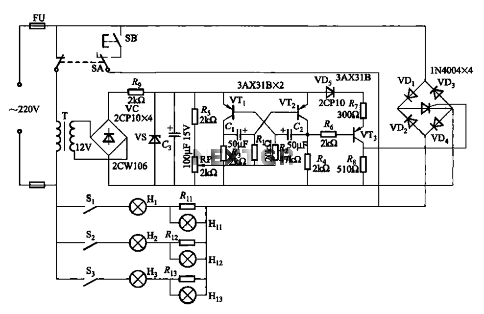
The self-excited multivibrator circuit utilizes transistors VTi and VT2 to generate an output signal that triggers a thyristor (VT3). An adjustment potentiometer (RP) is incorporated to modify the oscillation frequency, which in turn adjusts the flashing cycles of lights...
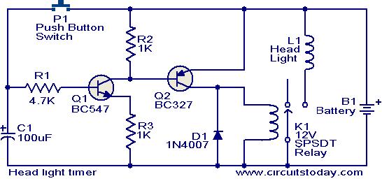
This circuit is a compact timer that keeps the headlights of a car on for approximately 1.5 minutes before turning them off. Incorporating this circuit into a vehicle allows access to dark areas without the need to return and...
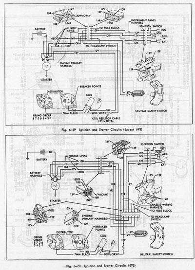
The system operates solely on vacuum. Upon inspection of the vacuum hoses, two brittle hoses were found that ran through the firewall to the headlight switch, where a slight hissing sound was noticeable when the lights were activated. Touching...
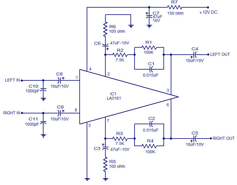
The LA3161 is an integrated two-channel preamplifier designed for car stereo applications. It operates on a 12V DC power supply. The LA3161 preamplifier is specifically engineered to enhance audio signals in automotive environments, ensuring optimal sound quality for car stereo...
Autonomous vehicles are currently utilized in various manufacturing facilities and are also marketed as toys. In the future, highways may be populated with vehicles that require no user intervention. Although this may not be fully realized, an autonomous vehicle...
Any type of flashing light on the main brake lights is prohibited and illegal in most states of the U.S.A. Verification is being conducted for the same in Canada. Meanwhile, using this circuit is at one's own risk, with...