
Kit Car Design & Build

The engine was allowed to run for a short period to drain oil into the sump and check for any condensation in the sight glass. Oil was drained into a clean container for inspection, with a little black residue being acceptable, but any signs of white indicating potential issues. The engine was run for five minutes with occasional throttle blips to bleed air from the cooling system, followed by fitting the radiator cap. An ultraviolet light was suggested for checking coolant leaks. The engine was restarted to reach the proper temperature, monitoring the temperature gauge, although caution was advised not to rely solely on it. After ensuring the engine reached a hot enough state, it was shut down to cool, and the oil was drained while still warm. Clean oil was to be refilled unless the drained oil appeared dirty, which would necessitate a filter change. Signs of a leaking head gasket were checked for by smelling the coolant and inspecting for oil films. The two spare connectors were identified as part of the Yamaha alarm system, with the need to refer to the Haynes wiring diagram for proper connections.
The electrical system of the motorcycle involves several components that require careful integration for optimal performance. The bike loom, which serves as the central wiring harness, is responsible for connecting various electrical elements, including the ignition switch, fuel pump, EXUP motor, and radiator fan switch. The connectors in question, associated with the optional Yamaha Cyclelock alarm system, must be addressed to ensure that the loom functions correctly. In instances where the alarm system is not installed, manufacturers often provide connectors with wires looped together to maintain circuit integrity.
The ignition switch is a critical component that controls the power flow to the electrical system. It is connected to the bike loom via a blue/black wire, which acts as a ground when the switch is activated. This connection ensures that the electrical components receive the necessary power when the ignition key is turned. The EXUP motor's operation is a positive indication that the electrical system is functioning properly, as it engages in a self-test cycle upon ignition.
The fuel pump's operation is also vital, as it is responsible for supplying fuel to the engine. The absence of leaks during testing indicates a sealed system, which is crucial for safe operation. The radiator fan switch serves a protective role, activating the fan to cool the engine when temperatures rise. Shorting this switch during testing provides a method to confirm its functionality without relying solely on the temperature gauge, which may not always provide accurate readings.
For maintenance, regular oil checks are essential. Draining oil while warm allows for better removal of contaminants, and inspecting the oil for signs of water contamination or excessive dirt can prevent significant engine issues. Furthermore, using a clean container for oil samples ensures accurate assessment of the oil's condition. The use of ultraviolet light for coolant leak detection is an effective method, as coolant fluoresces under UV light, making leaks easily identifiable.
In conclusion, the integration and testing of the electrical system, along with proper maintenance practices, are crucial for ensuring the reliability and performance of the motorcycle. The identification of the alarm system connectors and their proper wiring, as per the Haynes manual, will complete the electrical setup and contribute to the overall functionality of the bike loom.The plumbing is done and the fuel system is done. Final checks on the electrical system are under way. More tidying up and testing of the bike loom. Nearly there. I`ve got onequery though. My 2003 loom has two unused connectors for an alarm system. To me, these appear to have to be connected to something in order for the rest of the loom to work but on the other hand, the alarm must be an option on the bike, so it not being present should not affect the operation of the electrics. Here`s hoping! With the last few wires connected up and tested, there is nothing left to do but apply some power. I connected the bike loom power to the ignition switch, ensured the fuel pump switch was off and turned the ignition key. I then immediately turned it off again, as something was making a nasty noise. Brain engaged, I realised that it was probably only the EXUP motor, so I tried again. The noise was coming from the EXUP motor and it goes through a test cycle, which is a good sign. No smoke either I flicked the fuel pump switch and it immediately started running. I could hear it getting slower as it built up pressure and then after about 4 seconds it stopped as expected.
Cool. And no petrol leaks too. Doubly cool. Short out the radiator fan switch just to make sure it is working and as a cross check in case the temp gauge does not show when it is getting too hot, then reconnect it to the switch. Do not run it for more than 4 or five minutes. Shut it down and let the oil drain down into the sump, take a look through the sight glass and check for condensation (a little is quite normal), Drain off some of the oil into a CLEAN container so you can take a good look at it.
A little black is no problem but any sign of white and you need to start to worry. Let it run for five minutes with occasional blips to throttle, this should help to bleed any air in the cooling system. Shut it down, and fit the radiator cap. If you have a source of ultra violet light it will be useful as the coolant shows up really easy under black light and is the best way to check for coolant leaks.
Now its time to get the motor up to proper temperature so start it again and let it run as before but for longer this time. If you have a temp gauge you just need to keep an eye on it but DO NOT TRUST IT. Just let it get up to temperature in its own time (it will take a little while). If all looks good leave it running to get it hot (you can give it a few revs now if your confidence is getting better).
If the temp gets up to red or the fans start to run then that is hot enough. Shut it off and let it cool down. Drain the oil into a CLEAN container while the engine is still good and warm, if if looks clean then just refill with some semi-synth quality bike oil (do not be tempted to use high performance car oils) if it is dirty then you should change the filter again, if it is white / milky then go and have a cry in your tea. Take the radiator cap off once it is cool and take a good sniff, can you smell petrol / exhaust fumes If you look into the coolant is there a oil film on the top These are typically signs of leaky head gaskets.
I was right in my initial analysis of the bike loom. The two spare connectors are for something called a `cyclelock`, which is the Yamaha alarm system and if it is not present, Yamaha provide some connectors with the right wires looped together. I don`t have these, so the question is, which ones At this point you need to refer to the Haynes wiring diagram for the R1, as the factory service manual wiring diagram does not show the cyclelock or its connectors.
From the Haynes manual wiring diagram, the pins from left to right are: 1. This goes to the ignition switch (as a blue/black wire). This is effectively earthed when 🔗 External reference
Related Circuits
This circuit is designed for use with inductive pick-up elements and dynamic microphones. Most soundcards feature a line input and a dedicated input for electret (condenser) microphones. To connect an inductive tape recorder head or a dynamic microphone, an...

When a carrier signal is modulated using amplitude modulation, four frequency components are produced. The first component is the modulating signal itself, the second is the carrier frequency, while the last two are the sum and difference of the...
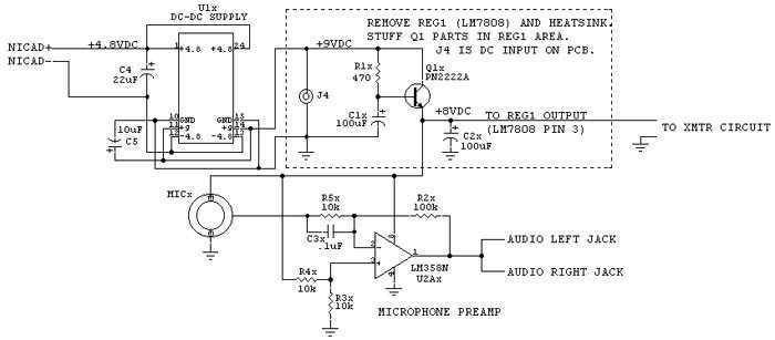
The improved system is called RC-CAM2. It works better and it costs less than my earlier attempt to get a wireless video system on my flying model. The only caveat is that there is some assembly (or disassembly as...
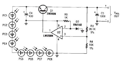
The circuit diagram illustrates a portable solar charger that utilizes an LM358N operational amplifier and a single transistor. This regulator delivers a constant output of 2.4 volts DC, suitable for powering small devices requiring energy from two AA battery...
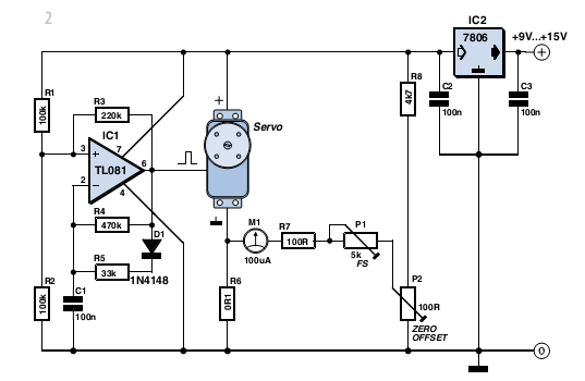
With some skill, an electronic scale can be constructed using a servo motor. Depending on the servo type, it can measure weights of up to approximately five kilograms (11 lbs) with reasonable accuracy. A detailed examination of the operating...
The IR Beam Breaker Circuit Diagram is designed as an infrared beam breaking alarm suitable for use in entryways or passageways. This circuit utilizes the well-known IR sensor module TSOP 1738, which detects 38 kHz infrared pulses emitted by...