
Car audio amplifier

The car audio amplifier circuit utilizes a dual amplifier configuration to enhance audio output effectively. The TDA2004 integrated circuit serves as the core of the amplifier, providing a robust platform for audio amplification. It is designed to operate with a supply voltage of +12 V, which is standard in automotive applications.
In a bridge configuration, two TDA2004 amplifiers are employed, allowing for increased output power. This setup effectively doubles the voltage swing across the speaker, leading to a theoretical output power of 40 watts. However, practical limitations, such as thermal dissipation and speaker impedance, may result in a maximum achievable output of around 20 watts.
The input stage of the circuit is connected to the output of the car's audio receiver, which provides the audio signal to be amplified. The output of the TDA2004 is then connected directly to the speaker. It is essential to ensure that the speaker is isolated from the vehicle's chassis ground to prevent potential damage to the amplifier. This isolation can be achieved by using isolated speaker terminals or employing a transformer to decouple the speaker from the ground.
Additionally, the circuit should include appropriate filtering capacitors at the power supply pins of the TDA2004 to ensure stable operation and minimize noise. Bypass capacitors close to the power supply pins can help in reducing high-frequency noise, ensuring a clean audio output.
In summary, this car audio amplifier circuit is a practical solution for enhancing the audio experience in a vehicle, providing a significant increase in output power while maintaining the integrity of the audio signal. Proper implementation of the circuit, along with attention to grounding and power supply decoupling, will yield optimal performance.Car audio amplifier schematic diagram. Given the voltage of the car is +12 V, we have the opportunity to take power over a threshold. The solution is to use two amplifiers in bridge connection, so the output quadrupled, at least theoretically, and at best, doubled. This 20w car audio amplifier circuit described hereoffers a20 wattboosterthatwillal low youtorealize thepower amplifierwith which one canincrease the poweroutputfromthe carstereoup to20Wattsmaximum. The inputINis connected to theoutputof thereceiver, Uoutputis connectedto the speakeras shownoncaraudioamplifierscheme.
It is veryimportanttoensurethat thespeakerhas no connection tothe chassis(ground)ifnot, the integrated circuitIC1, aTDA2004will. 🔗 External reference
Related Circuits
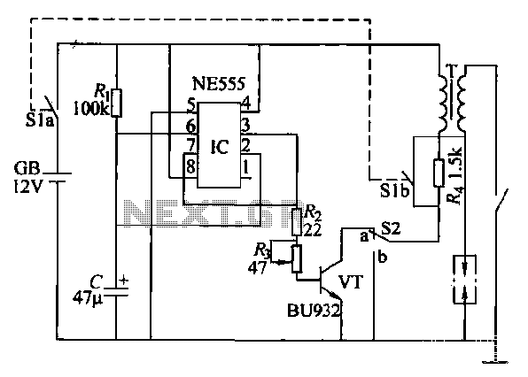
This paragraph describes an easy car alarm circuit that utilizes fewer components and is simple to produce. The circuit consists of an automobile anti-theft alarm system based on the NE555 timer, a power switch (VT), and a switch (S2),...
The TDA8932B/33(B) can operate with a symmetrical power supply. In this configuration, three half supply voltage buffers are disabled when powered from a symmetrical source. The TDA8932B/33(B) is a high-efficiency Class D audio amplifier designed for various audio applications. Operating...

A lens is a custom view of the content in the repository. It can be considered a sophisticated type of list that allows users to view content through the perspectives of trusted organizations and individuals. Class D amplifiers exhibit...
This is a straightforward, cost-effective Hi-Fi quality power amplifier. It can be constructed in five different configurations, as indicated in the table, ranging from 20 W to 80 W RMS. This Hi-Fi quality power amplifier is designed to deliver high...
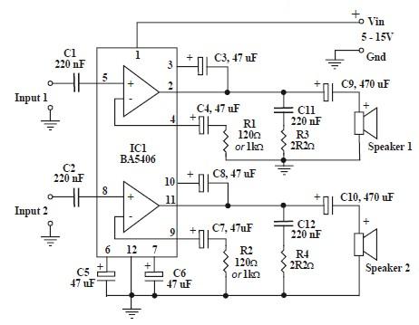
This circuit is based on the BA5406 audio integrated circuit and is capable of providing a maximum output power of 3 watts per channel. This audio circuit is designed for various applications requiring amplified sound output. The BA5406 is a...
This circuit has been designed to alert the vehicle driver that he has reached the maximum fixed speed limit (i.e. in a motorway). It eliminates the necessity of looking at the tachometer and to be distracted from driving. There...