
Car Battery Charger

The lead-acid battery charger circuit typically consists of several key components that work together to ensure safe and effective charging. The primary components include a transformer, a rectifier, a voltage regulator, and various protection elements.
The transformer steps down the AC voltage from the mains to a lower AC voltage suitable for charging. This lower voltage is then fed into a rectifier, which converts the AC voltage into DC voltage. A common choice for the rectifier is a bridge rectifier configuration, which utilizes four diodes arranged in a bridge formation to efficiently convert the AC input.
After rectification, the DC voltage may require regulation to ensure that the charging voltage does not exceed the battery's specifications. A voltage regulator, such as a linear regulator or a switching regulator, can be employed to maintain a constant output voltage. This is critical to prevent overcharging, which can damage the battery or reduce its lifespan.
Additionally, the circuit may incorporate protection features such as fuses or circuit breakers to safeguard against overcurrent conditions, as well as diodes to prevent reverse polarity connections. An LED indicator can also be included to signal when the charger is active, providing visual feedback to the user.
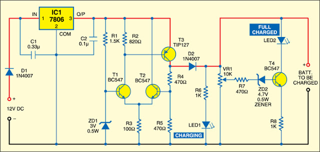
The circuit diagram included with the project will illustrate the connections between these components, detailing the input and output terminals, as well as any additional features such as adjustment potentiometers for fine-tuning the output voltage. This project is suitable for hobbyists and professionals alike, offering a practical solution for charging lead-acid batteries efficiently and safely.This charger will quickly and easily charge most any lead acid battery. Electronics project, easy to build, with circuit diagram included.. 🔗 External reference
Related Circuits
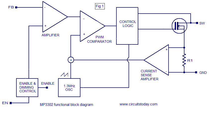
The MP3302 is a boost converter integrated circuit (IC) specifically designed for LED drive applications. It is capable of driving 27 LEDs, arranged as 9 strings of 3 white LEDs in series, powered by a lithium-ion battery. The IC...
Savings on electricity bills can be achieved by utilizing alternative power sources. The photovoltaic module or solar panel described here has a power output of 5 watts, providing 16.5V under full sunlight conditions, with a current delivery of 300-350...

This circuit switch slowly on and off the internal lights in a car. The delaying time can be adjusted changing the values of the 10k, 4M7 resistors and capacitor. More: The BUZ74 can handle voltages of 500V, but you...
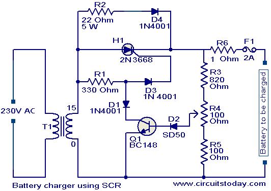
A simple battery charger based on SCR is presented. The SCR rectifies the AC mains voltage to charge the battery. When the battery connected to the charger is discharged, the battery voltage decreases, inhibiting the forward bias voltage from...
The difficulty of connection vga of a videocard to the TV set is, that Frequency of lower case development(display) of the TV set makes 15 KHz, and VGA card - from 31 KHz and is higher. Translation of development(display)...
There is no need to be disappointed the next time your digital camera displays a low battery indication during a picnic trip. Simply connect this digital camera adapter to the cigarette lighter outlet of your car and link the...