
Battery charger circuit using SCR

The schematic of the simple SCR-based battery charger consists of several key components that work together to ensure efficient charging of the battery. The circuit begins with the AC mains input, which is connected to the SCR (H1). The SCR functions as a controlled rectifier, allowing current to flow in one direction once it is triggered. The triggering mechanism is crucial for the operation of the charger.
When the battery voltage drops below a certain threshold due to discharge, the lack of sufficient forward bias at the base of transistor Q1 causes it to turn off. This condition allows the voltage at the gate of the SCR to rise, as it receives triggering voltage through resistor R1 and diode D3. Once the SCR is triggered, it begins to conduct, allowing the AC mains voltage to be rectified and supplied to the battery via resistor R6, which limits the current to prevent damage to the battery during charging.
As the battery charges and reaches its full capacity, the voltage divider formed by resistors R3, R4, and R5, along with diode D2, provides the necessary forward bias to turn transistor Q1 back on. This action cuts off the triggering voltage to the gate of the SCR, causing it to turn off and halt the main charging current. At this point, a small trickle charge can still flow to the battery through R2 and diode D4, ensuring the battery remains topped off without overcharging.
The design of this charger is inherently limited to slow charging due to the half-wave rectification of the input voltage. For applications requiring faster charging times, a full-wave rectification circuit would be necessary to provide a higher average voltage and current to the battery. Overall, this SCR-based charger is a simple and effective solution for maintaining battery charge in low-demand applications.A simple battery charger based on SCR is shown here. Here the SCR rectifies the AC mains voltage to charge the battery. When the battery connected to the charger gets discharged the battery voltage gets dropped. This inhibits the forward biasing voltage from reaching the base of the transistor Q1 through R4 and D2. This switches off the transistor. Whe n the transistor is turned OFF, the gate of SCR (H1) gets the triggering voltage via R1 & D3. This makes the SCR to conduct and it starts to rectify the AC input voltage. The rectified voltage is given to the battery through the resistor R6(5W). This starts charging of the battery. When the battery is completely charged the base of Q1 gets the forward bias signal through the voltage divider circuit made of R3, R4, R5 and D2. This turns the transistor ON. When the Q1 is turned ON the trigger voltage at the gate of SCR is cut off and the SCR is turned OFF.
In this condition a very small amount of charge reaches the battery via R2 and D4 for trickle charging. Since the charging voltage is only half wave rectified, this type of charger is suitable only for slow charging.
For fast charging full wave rectified charging voltage is needed. 🔗 External reference
Related Circuits
The circuit is designed to operate with an external power supply, which is why it does not include a transformer, rectifier, or filter capacitors in the schematic. However, these components can be added if desired. To utilize the circuit,...
The two circuits below illustrate using the 555 timer to close a relay for a predetermined amount of time by pressing a momentary N/O push button. The circuit on the left can be used for long time periods where...
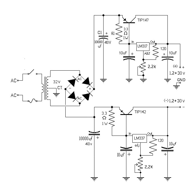
The 10A variable power supply circuit is symmetrical and can provide a symmetrical output voltage ranging from ±1.2 volts to ±30 volts DC, with a maximum current of 10A. This circuit utilizes symmetrical variable voltage regulators LM317 and LM337,...
This circuit enables the brake light to flash. The default behavior occurs when power is supplied to the circuit or when the brake is engaged. The timer IC (IC2) drives current to the transistor (Q2), producing an oscillating output...

If the total circuit resistance can be significantly reduced to less than 0.1 Ohm and a load of 0.4 Ohm or less is connected, over 1 kilowatt of free electrical energy can be obtained. There are two discrete voltage...
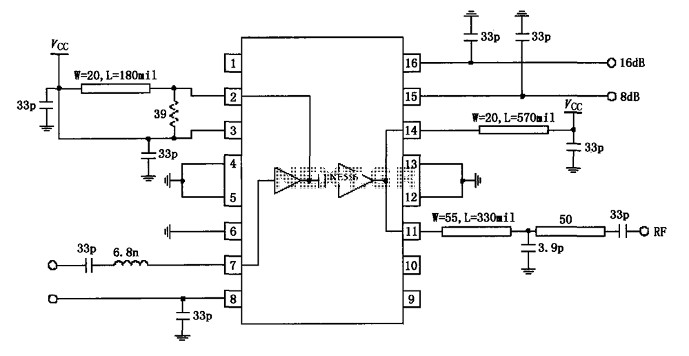
The circuit diagram illustrates the application of a 915MHz RF2155 power amplifier. The radio frequency (RF) signal enters through pin 7, where it is processed by a preamplifier. The output from the preamplifier is further amplified by the power...