
Car battery monitor

The circuit comprises a battery voltage monitoring system utilizing a light-emitting diode (LED) as a visual indicator. The design incorporates a 10 K ohm potentiometer that allows for the adjustment of the voltage threshold at which the LED will activate. This threshold is crucial for determining the acceptable operating voltage range for the battery.
When the system is powered, the battery voltage is continuously monitored. If the voltage drops below the set threshold due to high current draw, such as during engine cranking, the voltage divider formed by the potentiometer and an additional resistor (if used) will trigger the LED. This LED serves as an alert to the user, indicating that the battery voltage has reached a critical level, which may suggest that the battery is either defective or in need of recharging.
The circuit can be implemented using a simple comparator configuration or an operational amplifier (op-amp) for more precise voltage detection. Additional components may include a resistor in series with the LED to limit current, ensuring the LED operates within its safe limits.
Overall, this circuit is an essential tool for monitoring battery health and ensuring that the vehicle's electrical system operates efficiently, preventing potential failures due to inadequate battery voltage.Warning light (LED) indicates when battery voltage falls below level set by 10 K pot Can indicate that battery is defective or needs charging if cranking drops battery voltage below preset "safe" limit.
Related Circuits
The TDA7088T can be used in mono portable and pocket radios. This is a bipolar integrated circuit. Here is one of the application circuit diagrams. The TDA7088T is a versatile bipolar integrated circuit designed specifically for mono FM radio applications,...

For optimal efficiency, set MAX_STEPPERS to the number of stepper motors being controlled, with a maximum limit of four. Motors are identified by indices 0, 1, 2, and 3. On the QCard, there is a trade-off between the number...

When USB power is present and the device needs to operate, VSupply is supplied directly by the USB, while a PMOS transistor isolates the battery from the supply. Resistor R3 ensures that the PMOS remains on when USB power...
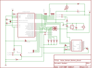
The project involves enhancing the Botanicalls system by integrating a solar panel that functions as both a light sensor and a battery charger for each plant. The complete circuit schematic is provided above, along with detailed images illustrating the...
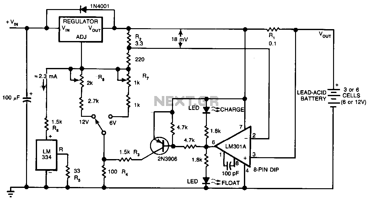
This circuit provides an initial voltage of 2.5 V per cell at 25°C to rapidly charge a battery. The charging current decreases as the battery charges, and when the current drops to 180 mA, the charging circuit reduces the...
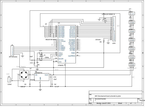
DTMF-based Robo Car design using the 8051 microcontroller project. This project demonstrates a method to control a domestic system using the DTMF tone generated by a telephone instrument when the user presses the keypad buttons of a mobile phone...