
Solar Botanicalls Sensor and Battery Boost

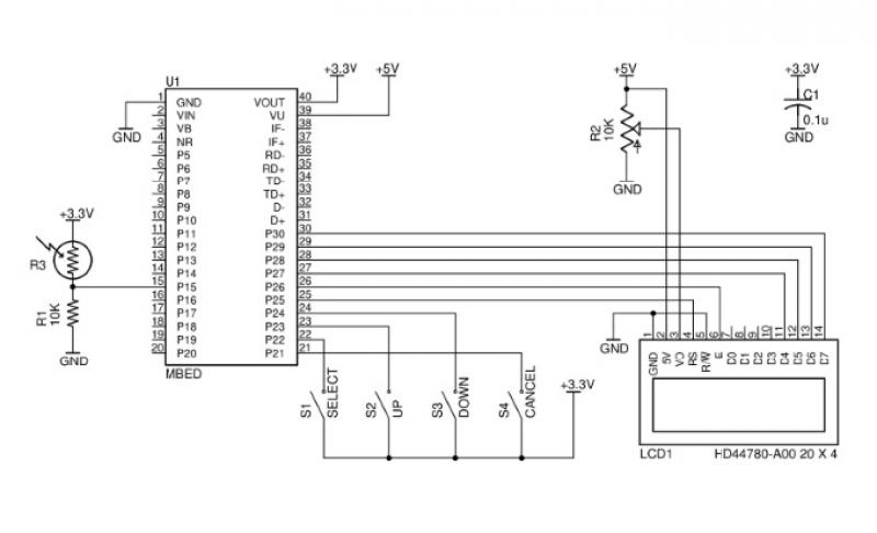
The proposed circuit design integrates a solar panel that serves dual purposes: it captures solar energy to charge a rechargeable battery and acts as a light sensor to monitor ambient light levels. This innovative approach is particularly beneficial for the Botanicalls project, as it allows for sustainable energy usage and real-time environmental monitoring of plants.
The circuit schematic features a solar panel connected to a battery management system. The solar panel is expected to generate an output voltage of approximately 3 volts under optimal sunlight conditions. This voltage is used to charge a 3 Volt rechargeable battery, which is essential for powering the Botanicalls system. The low-drop voltage regulator is included in the design to ensure that the voltage supplied to the rest of the circuit remains stable and within the operational limits of the components, despite variations in the solar panel output due to changing light conditions.
The light sensor component of the circuit is crucial for the system's functionality. It will continuously monitor the light levels and provide feedback to the Arduino microcontroller. The microcontroller will process this information to determine whether the plant needs additional light or if the solar panel is functioning efficiently. This feedback loop is important for optimizing plant care and ensuring that the Botanicalls system operates effectively.
The next phase of the project involves assembling the described sub-circuit on a test breadboard. This will allow for practical experimentation with various solar panels and battery types. The performance of each combination will be evaluated to determine the most effective setup for charging and light sensing. The Arduino microcontroller will facilitate data collection and analysis, enabling adjustments to the circuit as needed based on real-time performance metrics.
Overall, the integration of a solar panel as a charging and sensing mechanism represents a significant advancement in the Botanicalls project, promoting energy efficiency and enhancing the overall functionality of the system.Working on augmenting Botanicalls with a solar panel that will act as both a light sensor and a battery charger for each plant in the project. The full circuit schematic is above with a detail showing the solar charge and sensor connections below.
We`re planning to try a 3 Volt rechargeable battery with a low-drop voltage regulator for our power supply. Click on each of the images for a full-size graphic. The next project steps will be to build the sub-circuit on a test breadboard, to see how well different panels are able to charge various batteries while sensing light values using the Arduino microcontroller. 🔗 External reference
Related Circuits
This file is copyrighted. The individual who uploaded this work and first used it in licensing holds the rights. The provided information indicates that the file is protected by copyright, with the rights belonging to the individual who initially uploaded...
This issue features articles on various measurement and sensor-related embedded design projects. Readers are encouraged to attempt similar projects and share their results. Starting on page 14, Petre Tzvetanov Petrov describes a multilevel audible logical probe design. Petrov notes...
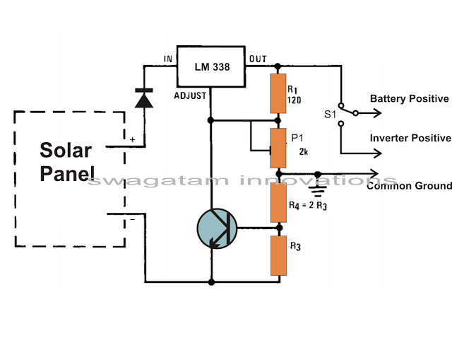
Solar panels are well-known devices that convert solar energy or sunlight into electricity. A solar panel consists of discrete sections of individual photovoltaic cells, each capable of generating a small amount of electrical power, typically between 1.5 to 3...
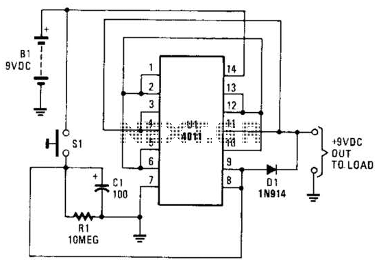
This battery saver circuit can automatically turn off a small piece of test equipment after a desired period of time, allowing for worry-free operation in a workshop environment. The circuit utilizes a CD4011 integrated circuit (IC) to function as...

12V Battery Charge Nominal Discharge (Low) Indicator Circuit. This circuit monitors car battery voltage and provides an indication of nominal supply voltage, as well as low or high voltage. The 12V Battery Charge Nominal Discharge Indicator Circuit is designed to...
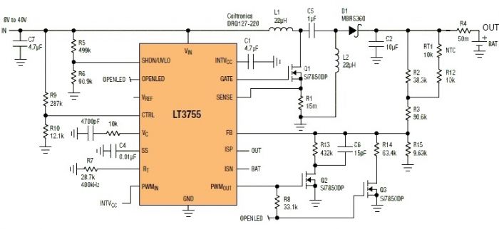
This Sealed Lead Acid Battery Charger is designed using the LT3755 DC-DC controller. The LT3755 is a DC-DC controller that operates as a constant-current source and supports a wide input voltage range from 4.5 to 40 volts, providing a...