
Precision Analog VU-meter Circuit


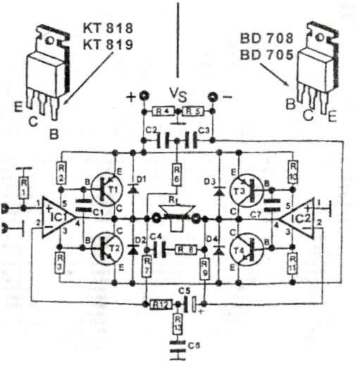
The theoretical circuit design consists of two identical circuits, each functioning as a power amplifier for its respective channel. Each channel is connected to a micro-ammeter through a bridge rectifier, which converts the alternating current into direct current, while the capacitors at each output enhance the instrument's inertia. Each channel features a trimmer at the input to adjust sensitivity. The diodes, connected in a back-to-back configuration, provide a logarithmic response characteristic for each channel.
Construction of the VU meter does not present any critical challenges. All components are mounted on a dedicated circuit board. The assembly process begins with the attachment of resistors and connections to the power supply and other external interfaces, concluding with the integration of the unique components. It is recommended to polish the materials to ensure they do not adhere improperly during assembly. Once completed, the voltage and corresponding signal inputs should be connected, and the trimmers adjusted so that there is no indication in the absence of a signal.
Electronic Components Needed:
| Component | Description |
|-----------|-------------|
| R1 | 120KΩ |
| R2 | 100KΩ TRIMMER |
| R3 | 100KΩ |
| R4 | 560Ω |
| R5 | 120KΩ |
| R6 | 100KΩ |
| R7 | 100KΩ |
| R8 | 560Ω |
| C1 | 1μF |
| C2 | 1μF |
| C3 | 10μF |
| C4 | 33μF |
| C5 | 1μF |
| C6 | 1μF |
| C7 | 10μF |
| C8 | 33μF |
| D1 | 4 x 1N4148 |
| D2 | OA85 |
| D3 | OA85 |
| D4 | 4 x 1N4148 |
| D5 | OA85 |
| D6 | OA85 |
| IC1 | TL082 |
The VU meter circuit provides a practical solution for visualizing audio levels in tube amplifiers, ensuring compatibility with traditional designs while maintaining the reliability and responsiveness necessary for accurate sound level monitoring. The use of analog components enhances the aesthetic appeal, making it a fitting choice for vintage audio equipment. Proper assembly and calibration are crucial for achieving optimal performance, ensuring that the meter operates accurately within the desired specifications.The vu-meter is distinguished in two categories, those with the needle instruments and those with the led column. Whether it is a tube amplifier or integrated amplifier, a vu-meter sound level meter is required. Today there are enough chips that do this work by using led to indicate the sound level. However, the amplifiers with LEDs are a retro version and consequently the indication of the led sound level would probably not fit in this case.
While an analogue display circuit would fit perfectly. The circuit is steady, reliable, fast in response (depending of course on the inertia of the instrument) and is visually suited to tube amplifiers.
The virtual circuit
The theoretical circuit of the structure is made up of two identical circuits based on a power amplifier that covers each channel. Each channel is an amplifier. At its exit we have connected a micro-ammeter via a bridge, which gives the sound level to each channel.
The bridge rectifies the alternating current and the capacitor present at each output increases the inertia of the instrument. At the input of each operator there is one trimer to regulate the sensitivity of each channel. The diodes that are wired, back to back, due to their linear function, create a logarithmic response to the characteristic transfer of each operator.
Construction
The construction does not show any critical points.
All materials are placed on the board designed for this purpose. Start building by first attaching the resistors and the connection to the power supply and other external connections and finish with the unique integrated construction.
Allow the materials to be polished to prevent them from sticking upside down. When finished, connect the voltage and signal the corresponding inputs of the construction. With the trimers that exist, adjust the instruments so that there is no indication in the absence of a signal.
| Electronic Components Needed | |||
|---|---|---|---|
| R1: 120KΩ R2: 100KΩ TRIMMER R3: 100KΩ R4: 560Ω R5: 120KΩ R6: 100KΩ R7: 100KΩ R8: 560Ω |
C1: 1μF C2: 1 μF C3: 10μF C4: 33μF C5: 1μF C6: 1μF C7: 10μF C8: 33μF |
D1: 4 X 1N4148 D2: OA85 D3: OA85 D4: 4 X 1N4148 D5: OA85 D6: OA85 IC1: TL082 |
|
Related Circuits
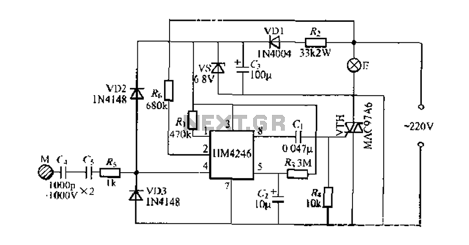
Development and production of a specialized touch dimmer integrated circuit. This circuit features four lighting functions: dark, medium, light, and a touch-sensitive trigger on all four sides. It has low harmonic radiation emission, high touch sensitivity, and stability. It...
This small transmitter can reach distances of more than 1 km under favorable transmission conditions. Modulation can be achieved using a microphone, such as an electret microphone, or another audio source. The transmitter includes a coil made of 5...
This audio amplifier circuit provides up to 200 W of high-quality output for loudspeakers with impedances ranging from 4 to 16 ohms. The operating voltage is between 24 and 36 V, with a maximum current of 5 A. The audio...
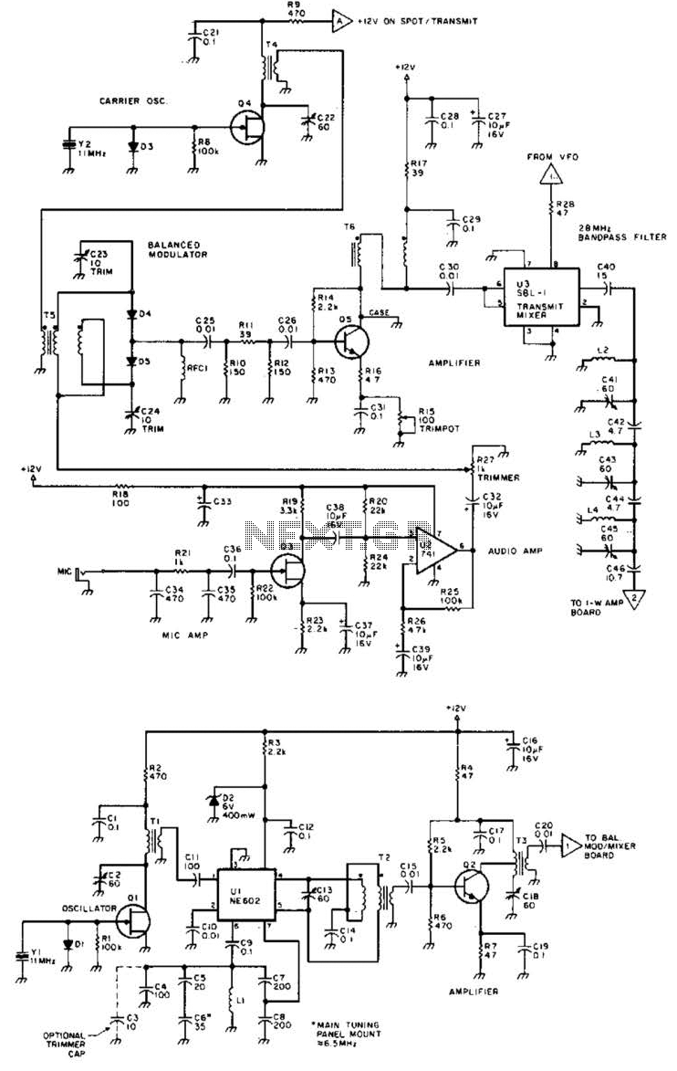
Using a Motorola MC2833 one-chip FM transmitter, a few support components, and an MPF6660 FET RF amplifier, this transmitter delivers approximately 3 W into a 50-ohm load. It is capable of operation over a frequency range of about 29...
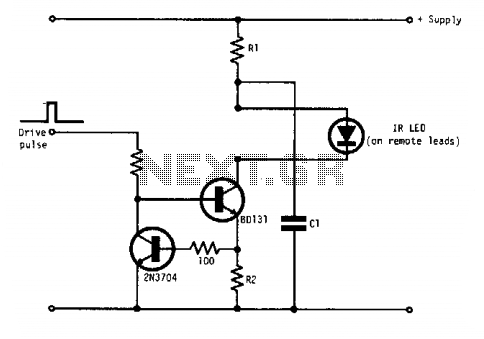
Q1 and Q2 form a constant current drive defined by R2. The current (I) approximates the reciprocal of R2 in the circuit shown for values of I greater than 1 amp. The pulse current is drawn from C1, which...
Very often when enjoying music or watching TV at high audio level, we may not be able to hear a telephone ring and thus miss an important incoming phone call. To overcome this situation, the circuit presented here can...