
car brake light or headlight flasher

This circuit employs a simple flashing mechanism suitable for automotive applications. The primary components include a timer IC (such as the 555 timer), which is configured in astable mode to generate a square wave output, effectively controlling the on-off cycling of the lamps.
The circuit is powered by the vehicle's 12-volt power supply, ensuring compatibility with standard automotive electrical systems. The two 10-watt lamps are connected in parallel to the output of the timer, allowing them to flash simultaneously.
To achieve the desired flashing effect, the frequency and duty cycle of the timer can be adjusted by changing the resistor and capacitor values connected to the timing pins of the IC. A typical configuration might use a capacitor in the range of microfarads and resistors in the kilo-ohm range to set a suitable flashing rate, which can be visually appealing and effective for signaling.
In addition to the timer, a transistor may be included in the circuit to handle the current required by the lamps, ensuring that the timer IC operates within its safe limits. A diode can also be integrated to protect against back EMF generated by the inductive load when the lamps are turned off.
Overall, this schematic provides an efficient and straightforward solution for enhancing vehicle safety through improved visibility of brake lights or headlights, making it a valuable addition to automotive lighting systems.The schematic shown here can be used as a circuit for Car brake light or headlight flasher for flashing two 10 watt 12 volt lamps in car or any vehicle. .. 🔗 External reference
Related Circuits
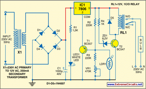
Voltage regulator ICs (78xx series) provide a steady output voltage against a widely fluctuating input supply when the common terminal is grounded. Any voltage above zero volts (ground) connected to the common terminal is added to the output voltage,...
This circuit allows the user to turn off a lamp using a switch located far from the bed, providing sufficient time to lie down before the lamp switches off. Due to its low current consumption, the circuit can be...
Dark Activated Switch or Porch Light Switch. This circuit activates a relay when the light level drops below a preset threshold. The light sensitivity can be adjusted using variable resistor VR1, and the relay contacts can control an external...
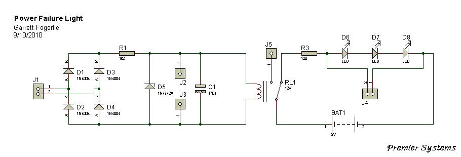
This is a very basic power failure lighting circuit based around a relay. This simple circuit has many uses, from lighting up rooms and walkways in the case of a power failure, to monitoring and security uses. There are...

A simple dimmer circuit can be constructed using the CMOS ICs TT8486A and TT6061A, allowing control over the intensity of an incandescent lamp through a touch contact. This electronic touch dimmer can increase the brightness of incandescent lamps in...

Only one channel of this circuit is shown. The other is practically identical. The input to the circuit, taken from the speaker output of a car radio, is divided into two paths. In one path, a high-power divider network...