
Power Failure Light

This power failure lighting circuit is designed to operate efficiently across a wide range of input voltages, from a minimum of 5 volts DC to a maximum of 240 volts AC. The circuit architecture is centered around a relay (RL1), which plays a crucial role in controlling the flow of power to the light-emitting diodes (LEDs) during normal and power failure conditions.
The circuit begins with the connection to AC power via connector J1. This AC voltage is then rectified to DC using a bridge rectifier composed of diodes D1 to D4. The rectification process converts the alternating current into a usable direct current, which is then smoothed by capacitor C1 to reduce voltage fluctuations and provide a stable DC output.
To maintain a consistent output voltage for the relay and LEDs, a 12-volt zener diode (D5) is employed in conjunction with resistor R1 and the coil resistance of relay RL1. This configuration ensures that the voltage supplied to the relay remains regulated at 12 volts, which is essential for the reliable operation of the relay.
Relay RL1 is a single-pole double-throw (SPDT) relay rated for 5 volts DC. When AC power is present, the relay is energized and opens the circuit to the LEDs (D6, D7, and D8), keeping them off. In the event of a power failure, the relay deactivates, allowing the circuit to close, and the backup power from battery BAT1 is activated. This battery, typically a 9-volt type, provides the necessary power to illuminate the LEDs, ensuring that the area remains lit during an outage.
The circuit also includes a provision for flexibility in power source selection. While BAT1 is specified as a 9-volt battery, the design allows for the use of various battery types depending on user requirements. Additionally, there is an option to connect a buzzer or other devices through connector J4, which is wired in parallel with the LEDs, enhancing the circuit's functionality for monitoring or alerting purposes.
The overall power consumption of the circuit is approximately 450 mW, making it energy-efficient while providing essential lighting and monitoring capabilities during power outages. This design is suitable for a variety of applications, including residential lighting, security systems, and other scenarios where reliable backup lighting is necessary.This is a very basic power failure lighting circuit based around a relay. This simple circuit has many uses, from lighting up rooms and walkways in the case of a power failure, to monitoring and security uses. There are many different power failure circuits out there based on 555 timers or transistors but they all have different problems including limited input voltage, price and complexity, and poor backup power.
This unit has been designed to work with mains power all the way down to 5 volts, and power 3 LEDs to provide light for a hallway or a child's room in the event of power failure. The PCB includes many simple add-ons and modifications too. This circuit is connected to ac power through J1 then rectified to dc through D1-D4. D5 is a 12 volt zener diode being used along with the resistor R1 and the coil resistance of relay RL1 to regulate the input voltage to 12 volts and C1 is used to help smooth this power. The relay RL1 is a SPDT 5vDc relay and when power is applied to it, it opens the circuit with the LEDs so they are off as long as power is on if the power goes off, the relay closes the circuit and the battery BAT1 powers the LEDs D6, D7, and D8.
In this circuit BAT1 is a 9 volt battery that powers the 3 LEDs through R3; however BAT1 can be many different batteries depending on your needs. J4 is also available in parallel with the LEDs to connect a buzzer or etc. Input Voltage Max: 240 Volts AC Input Voltage Min: 5 Volts DC Approximant Power Consumption: 450 mW
🔗 External reference
Related Circuits
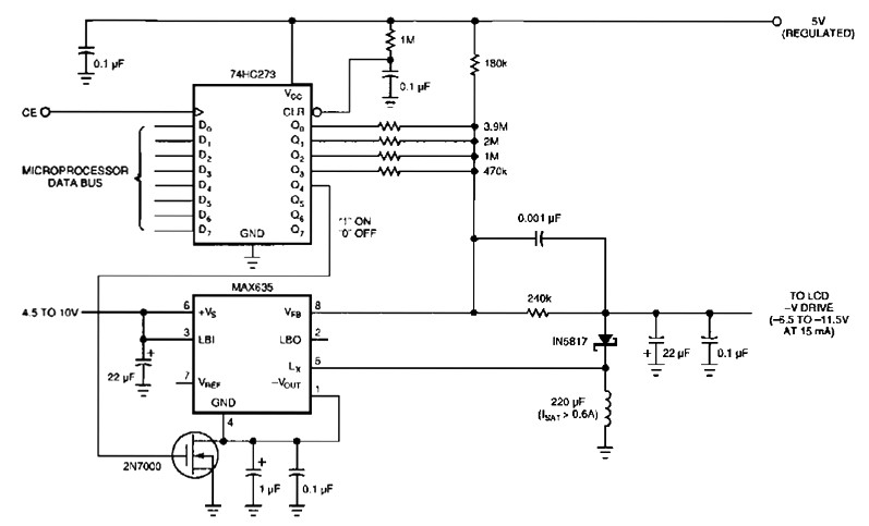
The following figure's switching regulator generates a negative voltage from the notebook battery supply. The microprocessor data bus drives a 4-bit DAC (74HC273), which can vary the regulator output between 6.5 to 11.5 V. This arrangement enables a staircase...

The components available were utilized to create a long-range FM radio transmitter operating within the 88-108 MHz band, designed for playing music. The circuit includes a power section that rectifies mains voltage to provide a stable 12V DC for...

A water Happy Valley-type four flashing lights string controller, electric bollard is designed for use with a type J Ding Japanese lantern. The circuit employs a specific integrated circuit (IC) utilizing CMOS technology. It features a black soft cream...
The following diagram illustrates a 50W offline switching power supply circuit design. The circuit is powered by a MOSFET, specifically the BUZ80A/IXTP4N8 for a 220V AC voltage input and the GE IRF823 for a 110V AC input voltage. The...
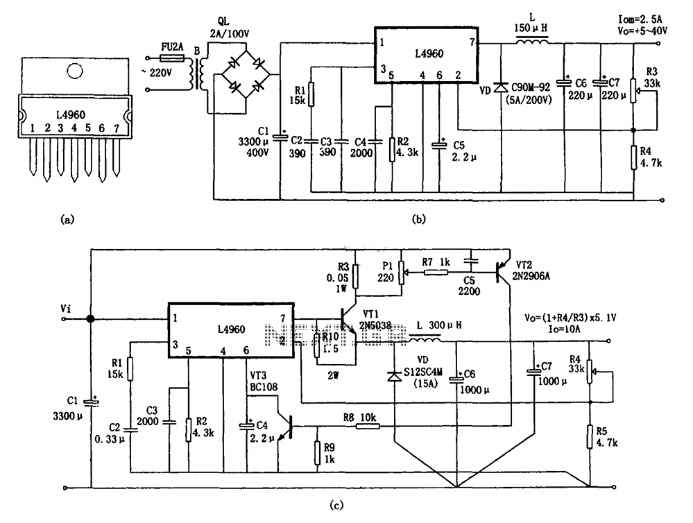
The circuit shown in the figure consists of an L4960 switching power supply that operates with an input voltage range of +5 to +40V. The AC 220V voltage is transformed down through a step-down transformer, followed by a bridge...

The R-C twin-tee passive circuit provides band-reject (notch) filtering suitable for portable applications. It has a loaded circuit Q of 0.25. Effective rejection is achievable when the bridge is balanced, which requires close tolerances of the adjustable components, and...