
Car clock temp voltmeter

To set the clock, the following steps are to be followed:
- Set the hours by pressing and holding a button, which will increment the minutes until reaching zero, then the tens of minutes until reaching zero, followed by the hours. The button should be released once the hours are correct.
- Set the tens of minutes by holding the button until the units of minutes increment to zero, followed by the tens of minutes. Release the button when the tens of minutes are correct.
- Set the units of minutes by holding the button until the units increment to the desired value. Release the button when the units are correct.
A 12V power source from the contact or light switch must be connected to PAD8 for backlighting, which activates when the engine is running or the lights are on, facilitated by IC4 (LM317) configured to output 4.1V (using resistors R3-R5). Continuous 12V power should be connected to PAD6, which is regulated down to 5V by IC2, the Microchip MCP1790, powering the PIC, LCD, and temperature sensor.
To avoid interference from the backlight, which can cause the temperature sensor to provide inaccurate readings, it is recommended to mount the sensor off the PCB and connect it with four wires. In certain applications, the backlight is activated by either the ignition or the lights through the use of two diodes connected to PAD8.
Clock accuracy is maintained using Timer1, which is driven by a 32.768 kHz quartz crystal. The timer typically generates an interrupt every two seconds, but the TMR1 value is set to approximately 8000h, reducing the interrupt frequency to once per second. Adjustments to the TMR1 value can be made to fine-tune clock speed, allowing for increased or decreased timekeeping accuracy. Non-integer values can also be utilized for precise control of the clock's timing.
The software is developed in C using the Hi-Tech C compiler, incorporating power-saving features such as Sleep() and wake-up functions triggered by Timer1 overflow. The programming environment required includes the Microchip MPLAB IDE (available for free) and a PICkit3 compatible programmer. The Hi-Tech C compiler's lite version is sufficient for this project. All relevant source code, header files, and project files are contained in a zip file, with the main project file named CarClockTempVoltMeter_5V.mcp and the workspace file named LCD_CarClockTempVoltMeter_5V.mcw.This device was designed to replace the original digital clock in a Fiat Ducato 1992-1994, mounted just above the inside rearview mirror. The original clock is not very accurate, only displays time and is sensitive to interference (e. g. from Xenon headlights). The replacement device described here does not have these disadvantages, and on top of t hat also displays the temperature and the car`s battery voltage. It works on the car battery and uses the Microchip MCP9800 as a temperature sensor. This circuit is based around the PIC16F1937 microcontroller. This chip is actually a small computer contained in a single chip, including RAM memory, EEPROM, I/O ports, CPU and so on. When you buy this chip, it comes empty with no program on it. You have to compile the source code and download the resulting machine code into it, using a PC and a small programmer attached to the PC and the chip.
To get yourself familiar with this stuff, I suggest you first read this link: Getting started with microcontrollers. - First set the hours. Press and hold the button, the units of the minutes will increase until reached 0, then the tens of minutes will increase until reached 0, then the hours will increase.
Release the button when the hours are correct. - Then set the tens of minutes. Press and hold the button, the units of the minutes will increase until reached 0, then the tens of minutes will increase. Release the button when the tens of minutes are correct. - Then set the units of minutes. Press and hold the button, the units of the minutes will increase. Release the button when the units of minutes are correct. 12V power coming from contact or light switch must be connected to PAD8. This is for the backlight, it will be on when the engine is running or when the light is on, by means of IC4 (LM317) which is configured for 4.
1V (R3-R5). 12V continuous power must be connected to PAD6. This is converted down to 5V by means of IC2, a very efficient power regulator by Microchip (the MCP1790) which provides the power for the PIC, the LCD and the temp sensor. - The backlight unit can get a little bit warm and this may mislead the temperature sensor. It is better to mount the sensor off the PCB and connect it with 4 wires. - In my motorhome the backlight goes on when either the contact is on or the light is on. This is achieved with two diodes on both lines from contact and from light to PAD8. - Clock accuracy: the time keeping is done using timer1, operated by a 32768 Hz quartz crystal. Normally, the timer causes an interrupt every 2 seconds, but since we set the TMR1 value to about 8000h, this is reduced to once a second.
You can play with the 8000h value: increasing it to e. g. 8001h will make the clock run a bit faster, decreasing it will make it run slower. You can even use non integer values, e. g. 8000. 5h by incrementing every x interrupts. Using long observation times for the accuracy, you can get the right value for TMR1, resulting in a very high accuracy clock. The software is written in C ( Hi-tech C supporting Microchip ). It uses power saving techniques such as Sleep() and wake up from sleep after timer1 overflow. For programming you need the Microchip MPLAB IDE (free to download) and a PICkit3 compatible programmer.
You also need the Hi-tech C compiler (the lite version, free to download, will do). Zip file containing all source code, header files and project files: Link to MPLAB project. The project file to open is called CarClockTempVoltMeter_5V. mcp, the workspace file is LCD_CarClockTempVoltMeter_5V. mcw. 🔗 External reference
Related Circuits
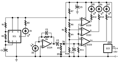
All distances mentioned can vary depending on the infrared transmitting and receiving LEDs used and are significantly affected by the color of the reflecting surface. Black surfaces greatly reduce the device's sensitivity. This circuit can also be applied in...
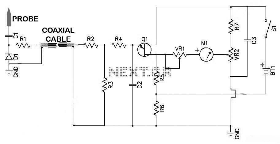
Sensitive RF Voltmeter Probe Circuit. This circuit measures RF voltages beyond 200 MHz and up to about 5 V. PARTS LIST: R1 - 4.7 MΩ, R2 - 1 MΩ, R3 - 1 MΩ, R4 - 100 kΩ, R5 -...
This precise one-pulse-per-second clock is constructed using a few common components and is driven by a 50 or 60 Hertz mains supply, without any direct connection to it. It produces a beep or metronome-like click and/or a visible flash...
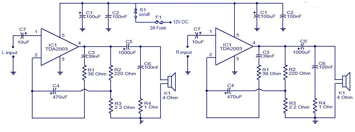
The circuit is easy to construct. The TDA2003 is an integrated radio amplifier from ST Microelectronics that features short circuit protection for all pins, thermal protection, low harmonic distortion, and low crossover distortion. In the circuit provided, the TDA2003...
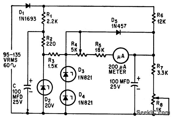
This circuit measures alternating current (AC) voltages in the range of 95 to 135 volts with an accuracy of 0.6%, utilizing a standard meter that has a 2% accuracy rating. The circuit employs Zener diodes to provide a stable...
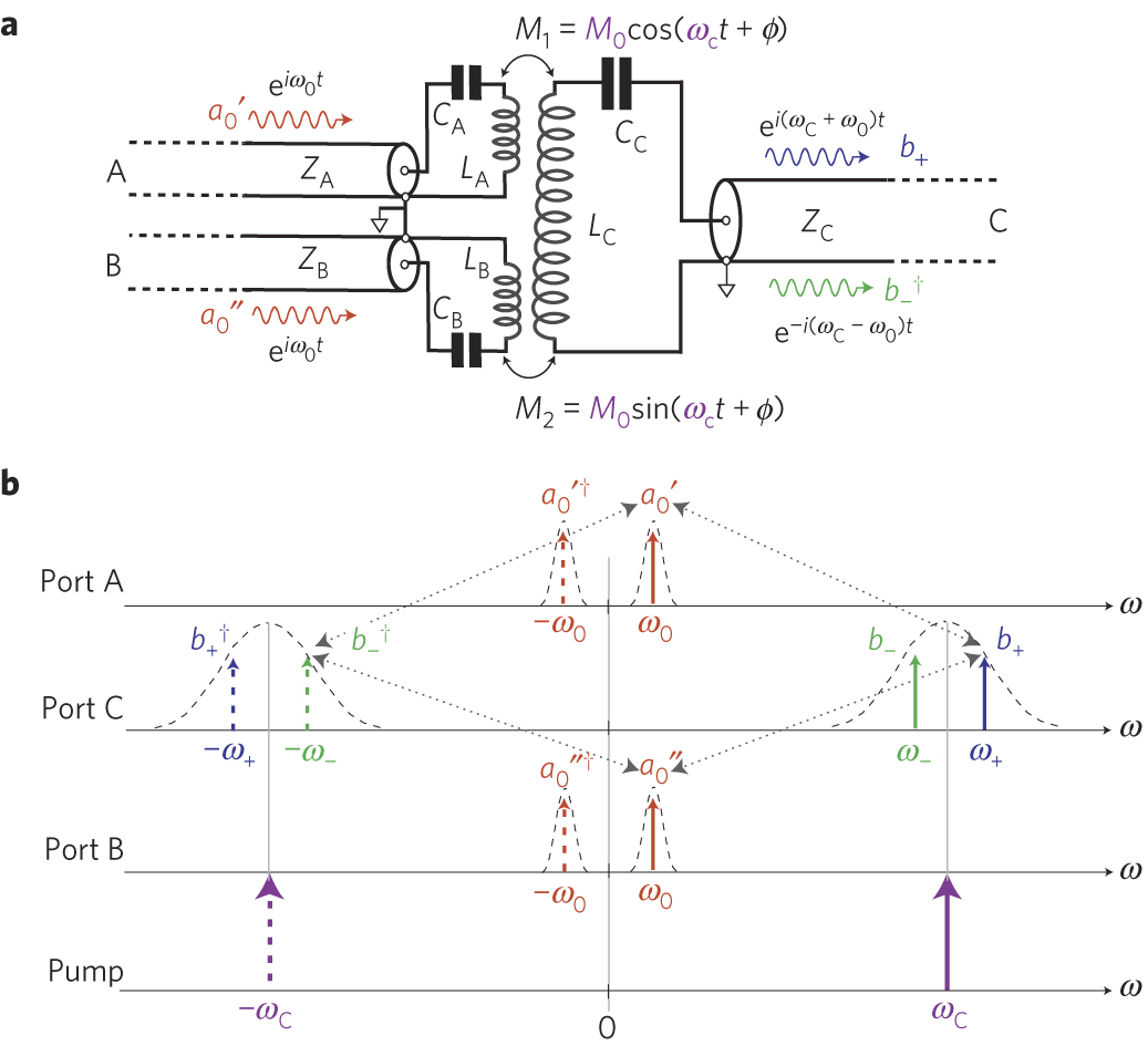
The circuit schematic of the UDC consists solely of dispersive components. Two low-frequency series LC resonators, with equal inductances (LA=LB) and capacitances (CA=CB), are connected to two input semi-infinite transmission lines, designated as A and B. These resonators are...