
Sensitive RF Voltmeter Probe

The Sensitive RF Voltmeter Probe Circuit is designed to accurately measure RF voltages in the frequency range exceeding 200 MHz, reaching up to approximately 5 volts. This capability makes it suitable for applications in RF testing, telecommunications, and various electronic circuit evaluations where high-frequency signals are present.
The circuit consists of several key components, including resistors, capacitors, and variable resistors (potentiometers), which are essential for setting the appropriate sensitivity and scaling of the voltage measurement. The resistors in the circuit, such as R1 (4.7 MΩ), R2 (1 MΩ), and R3 (1 MΩ), are utilized to create a voltage divider, allowing the circuit to handle high input voltages while providing a manageable output voltage for further processing or display.
Capacitors C1 and C2 (both 0.001 µF disc ceramic) serve as coupling capacitors, blocking any DC component while allowing the AC RF signals to pass through. This ensures that only the RF voltage measurements are considered, eliminating potential interference from DC bias levels. Additionally, C3 (0.1 µF) may be used for filtering purposes, stabilizing the circuit against high-frequency noise.
Variable resistors VR1 and VR2 (both 2 kΩ) are included to allow for calibration and adjustment of the circuit's response, enabling the user to fine-tune the sensitivity based on the specific application or measurement requirements.
The diode D1, likely a 1N series diode, may be employed for rectification purposes, converting the AC RF voltage into a DC voltage that can be measured more easily. This conversion is crucial for displaying the voltage on a standard multimeter or analog meter.
Overall, the design of the Sensitive RF Voltmeter Probe Circuit emphasizes precision in measuring high-frequency signals while maintaining ease of use through adjustable components. This circuit is an invaluable tool for engineers and technicians working in RF applications, providing reliable measurements in a compact and efficient manner.Sensitive RF Voltmeter Probe Circuit This Circuit measures RF voltages beyond 200MHz and up to about 5V. PARTS LISTR14.7M?R21M?R31M?R4100k?R5330?R610k?R710k?VR12k?VR22k?C10.001µF (Disc Ceramic)C20.001µF(Disc Ceramic)C30.01µFD11N..
🔗 External reference
Related Circuits
An analog meter typically does not exhibit high impedance due to the absence of a buffer circuit within its design. By incorporating active buffering, the input impedance of this circuit can be significantly enhanced. The integration of an active buffer...
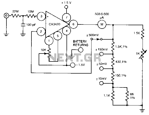
A resistance of 1,000,000 MΩ takes advantage of the high input impedance of the CA3420 BiMOS op-amp. Only two 1.5-V AA-type penlite batteries are required for use. Full-scale deflection is ±500 nV, ±150 mV, and ±15 mV. The circuit utilizes...
The UTC A6966 is designed for driving a 5 LED level meter and comes in a 9-lead SIP package. It includes one input amplifier and five comparators for LED level indication. Manufactured by LianShun Electronics Co., Ltd. The UTC A6966...
The circuit is a comparator that measures the voltage of a car battery in steps of 1 Volt. The voltage measurement is performed by comparing the battery voltage, applied to the inverting inputs of amplifiers, against reference voltages produced...
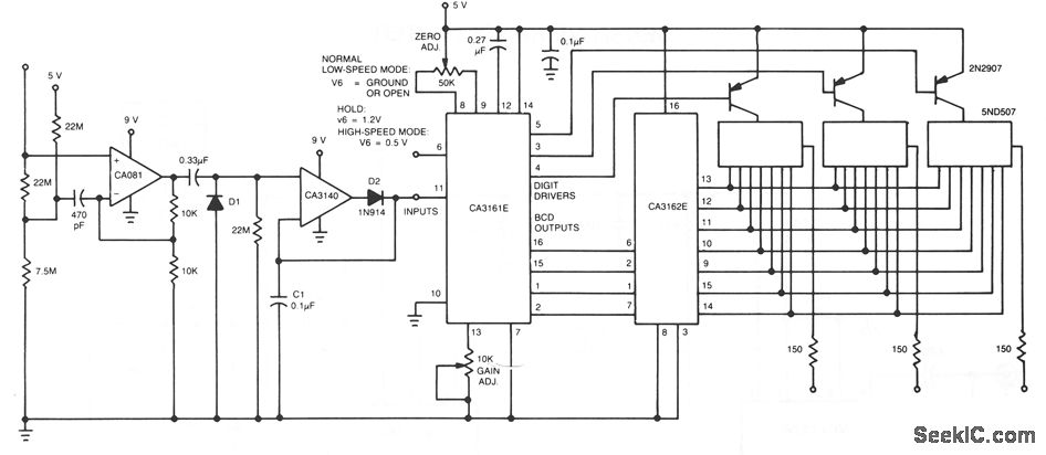
The CA081 and CA3140 BiMOS operational amplifiers provide minimal loading on the circuits being measured. The wide bandwidth and high slew rate of the CA081 enable the meter to operate at frequencies up to 0.5 MHz. The CA081 and CA3140...
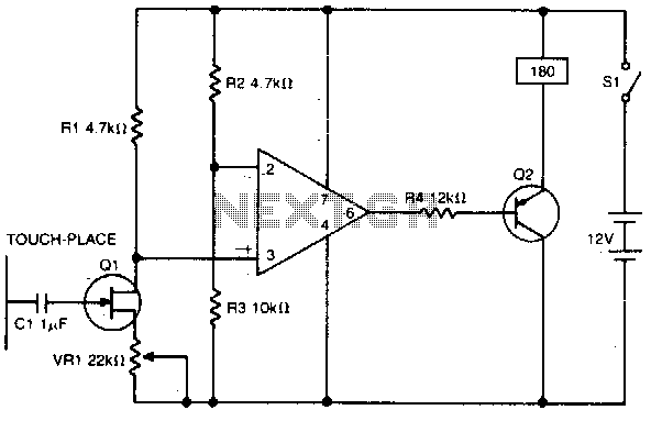
A high impedance input is provided by Q1, a general-purpose field effect transistor. The 741 operational amplifier is utilized as a sensitive voltage level switch, which subsequently activates Q2, a medium current PNP bipolar transistor. This action energizes a...