
battery tester circuit schematic

A battery tester is an essential tool for diagnosing battery health and functionality in various electronic devices. The basic design of a battery tester typically includes a simple circuit that can measure voltage and, in some cases, load testing capabilities to assess the battery's performance under operational conditions.
The schematic for a basic battery tester may consist of the following components:
1. **Power Supply**: A small power source, such as a 9V battery, to power the tester circuit itself.
2. **Voltage Divider**: A resistor network that scales down the voltage of the battery being tested to a level that can be safely measured.
3. **Microcontroller or Analog Meter**: A microcontroller can be used to interpret the voltage readings and display them on an LCD screen, while a simpler analog meter can provide a direct voltage readout.
4. **Load Resistor**: This component is used to apply a known load to the battery, allowing for a more accurate assessment of its ability to deliver current.
5. **Switch**: A toggle switch to select between testing modes, such as voltage measurement and load testing.
6. **Output Display**: LEDs or an LCD screen to indicate the battery status, such as "Good," "Weak," or "Replace."
When constructing a battery tester, it is important to ensure that the components are rated appropriately for the maximum voltage and current that may be encountered. The circuit should be housed in a durable enclosure to protect it from physical damage and ensure longevity. Additionally, proper labeling and clear instructions should accompany the device to guide users in its operation.
In summary, a battery tester is a valuable tool that can save time and money by diagnosing battery issues before resorting to professional repair services. The design and construction of such a device can be straightforward, making it accessible for those with basic electronics knowledge.Is the battery empty, or is there something wrong with the device? That s always a difficult question when your walkman or some other battery-powered device appears to be dead when you switch it on. Before you take it to the shop for servicing, the first thing you should do is to test the battery or batteries.
Of course, this means you need a reliable battery tester, but it also means you can limit the damage to the cost of a battery or two and a one-time investment of time and money in building a suitable tester.. 🔗 External reference
Related Circuits
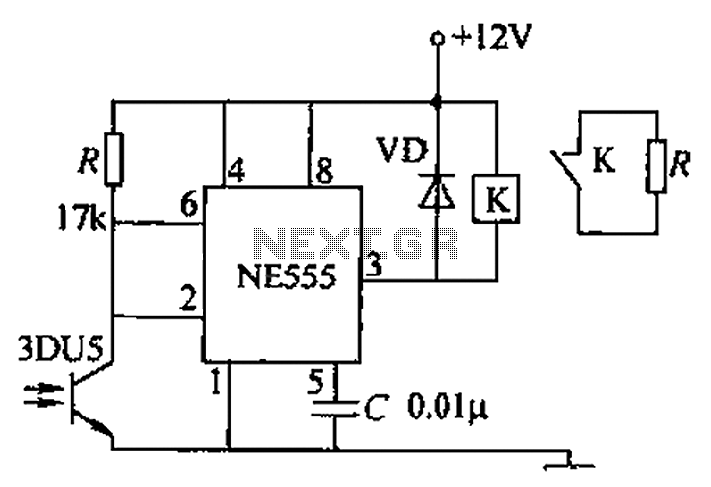
A transmitting circuit powered by an infrared light-emitting diode emits light. The receiving circuit, shown in the figure, utilizes a transistor (3DU5) to receive the infrared light and output the received signal. The signal is sent to terminal 3...
This sensitive touch potentiometer utilizes IC1 (CA3130), an operational amplifier known for its high input impedance. When a finger touches the Se1 sensor, C2... This circuit design incorporates a touch-sensitive potentiometer that leverages the CA3130 operational amplifier to achieve high...
This circuit can replace the single current-limiting resistor commonly found in inexpensive battery chargers. The alternative presented here will prove beneficial as it prevents the premature disposal of NiCd batteries after approximately three months of inadequate charging. The circuit...
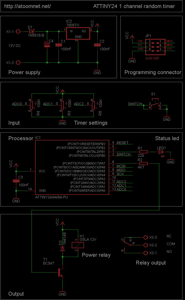
This random timer circuit is based on an Atmel ATTINY24 AVR driving one power relay. It can be used to switch on and off other circuits randomly. For instance, in a model railroad setup, this circuit can activate and...

This automatic light dimmer circuit enables controlled lighting that gradually turns on or off. The operation is as follows: when switch S1 is closed, capacitor C1 charges slowly. Once the voltage across C1 reaches 0.6 volts, transistor T1 begins...
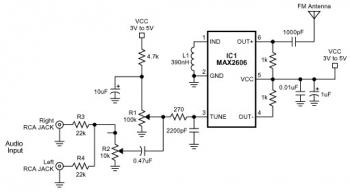
The FM transmitter circuit is built using a single MAX2606 chip. This simple FM transmitter connects a home entertainment system to a portable radio, allowing music to be played in one room and listened to in another, such as...