555 meter circuit diagram of a simple cavers
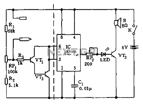
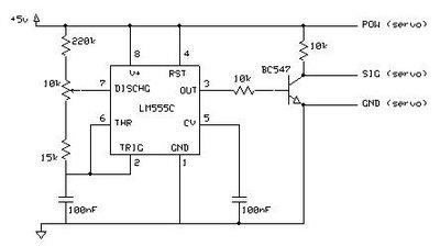
The apparatus consists of a cavers point detection circuit and a triggering display circuit. The cavers instrument functions as a test probe, which, when held in one hand, can detect acupuncture points by touching the skin with another probe. When the probes approach or make contact with acupuncture points, the low resistance between the two electrodes causes the transistors VT1 and VT2 to enter saturation conduction. This results in pin 2 of the 555 timer IC going low, which sets the IC and allows transistor VT3 to conduct. This action generates a visual and audible display signal indicating the detection of an acupuncture point. Conversely, when the probes are not in contact with acupuncture points, the higher skin resistance causes transistors VT1 and VT2 to turn off, resetting the 555 timer IC and producing a silent light signal.
The cavers point detection circuit operates on the principle of measuring skin resistance to identify acupuncture points. This circuit employs a pair of electrodes that serve as the probes. When one probe is held and the other is used to touch the skin, the circuit detects changes in resistance. Acupuncture points exhibit lower resistance compared to non-acupuncture points, which is a critical factor for the detection mechanism.
The circuit includes two main components: the detection circuit and the display circuit. The detection circuit is primarily based on the configuration of transistors VT1 and VT2, which are configured as a differential pair. When the probes are in proximity to an acupuncture point, the low resistance allows for a significant current flow, saturating the transistors and activating the 555 timer IC.
The 555 timer is configured in a monostable mode, where it is triggered by a low signal at pin 2. When this occurs, the output at pin 3 goes high, activating VT3, which drives the display components. The visual display may consist of LEDs that light up, while the audible signal could be generated by a piezo buzzer or similar device. The combination of visual and audible signals provides immediate feedback to the user regarding the detection of acupuncture points.
In contrast, when the probes are not in contact with acupuncture points, the increased skin resistance results in the transistors VT1 and VT2 turning off. This state resets the 555 timer IC, leading to a silent condition with a light signal that indicates no acupuncture points are detected. The design ensures that the user receives clear and distinct feedback depending on the state of the probes, enhancing the usability of the cavers instrument for practitioners in acupuncture and related fields.
Overall, the apparatus is a straightforward yet effective tool for detecting acupuncture points, integrating electronic components that provide reliable performance and user-friendly operation. As shown, the apparatus includes cavers point detection circuit and triggering display circuit. The cavers instrument is a test probe grip in the hands of another probe touches the skin, when approaching or touching the acupuncture points, due to the low resistance between the two electrodes, so that VT1, VT2 composite tube saturated conduction, 555 feet 2 was low, the IC is set, VT3 conduction, visual and audible display signal that points to detect quasi; non-acupuncture points, due to the large skin resistance, VT1, VT2 off, 555 in the reset state, silent light signal.
