
Car Large capacitor charge controllers

The circuit described involves a one-farad capacitor which serves as an energy storage element, commonly used in applications requiring high capacitance for smoothing voltage fluctuations or providing bursts of power. The necessity of pre-charging the capacitor with a current-limiting resistor is critical to prevent damage to both the capacitor and the power source. The resistor limits the inrush current when the capacitor is initially connected to the power supply, avoiding a sudden surge that could lead to failure.
The circuit also includes a basic cap switch designed to connect the capacitor to ground only when it reaches a voltage threshold of 0.4-0.7V below the battery voltage. This feature prevents the capacitor from discharging too quickly, allowing for controlled energy release. The implementation of a 22 Ohm resistor in the charging path serves dual purposes: it limits the current to a safe level during charging and can also function as a low-power load, such as a 12V lightbulb, providing visual feedback of the circuit's operation.
The N-channel MOSFET (T1), such as the IRF1010, IRFP054, IRF048, or P60N06, is employed for its low on-resistance characteristics, enhancing efficiency during operation. When the capacitor is discharging, T1 operates in reverse conduction mode, akin to the behavior observed in synchronous rectifiers. This means that the MOSFET allows current to flow from the source (the capacitor) to the drain (the load) when the circuit is active, thereby facilitating the discharge process while minimizing energy loss.
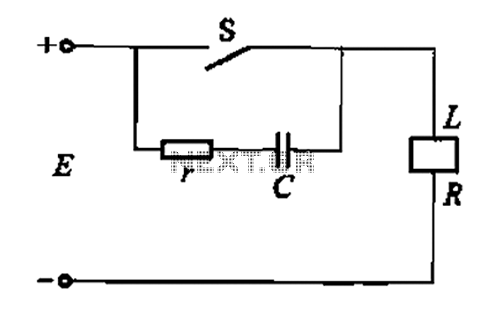
The careful design of this circuit ensures both safety and efficiency in applications involving large capacitors, making it suitable for various electronic projects where energy storage and management are crucial. Proper component selection and understanding of the operational principles are essential for effective implementation.One-farad capacitors require some care. It`s a common knowledge that they must be pre-charged with a current-limiting resistor before plugging in. It is less common knowledge that those fifty-dollar `smart cap controllers` are in fact very simple devices, two dollars for parts and labor.
Here`s a basic cap switch that will connect capacitor to ground only when it`s charged to within 0.4-0.7V from battery voltage (otherwise, it`s charging through a 22 Ohm resistor, which can be a low-power 12V lightbulb, too). Note that when the circuit is open, and a high current draw starts dicharging the capacitor, T1 (N-MOS with low channel resistance - IRF1010, IRFP054, IRF048, P60N06 etc) is actually conducting in reverse direction (as in syncronous rectifiers: S->D no 🔗 External reference
Related Circuits
Charge your iPod without connecting it to a computer! Using the USB port on your computer to charge your player's batteries is not always practical. To facilitate the charging of an iPod without the necessity of a computer, a dedicated...
This circuit illustrates a Car Radio Audio Amplifier using the TDA2003 integrated circuit. The datasheet for the TDA2003 includes electrical characteristics and schematic wiring details. The TDA2003 is a high-performance audio amplifier designed for automotive applications. It is capable of...
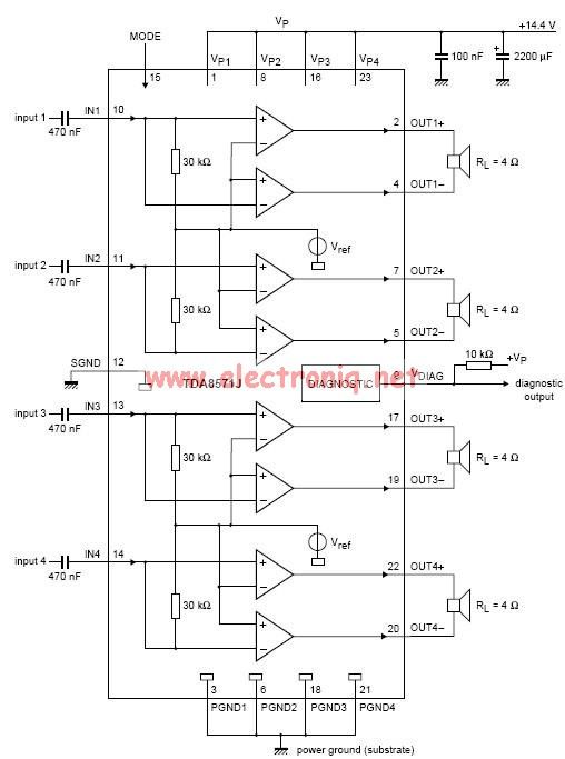
This electronic circuit diagram represents an audio power amplifier utilizing the TDA8571J integrated circuit. It is a class-B output amplifier configured in a BTL (Bridge-Tied Load) arrangement, featuring four amplifiers, each with a gain of 34 dB. The main...
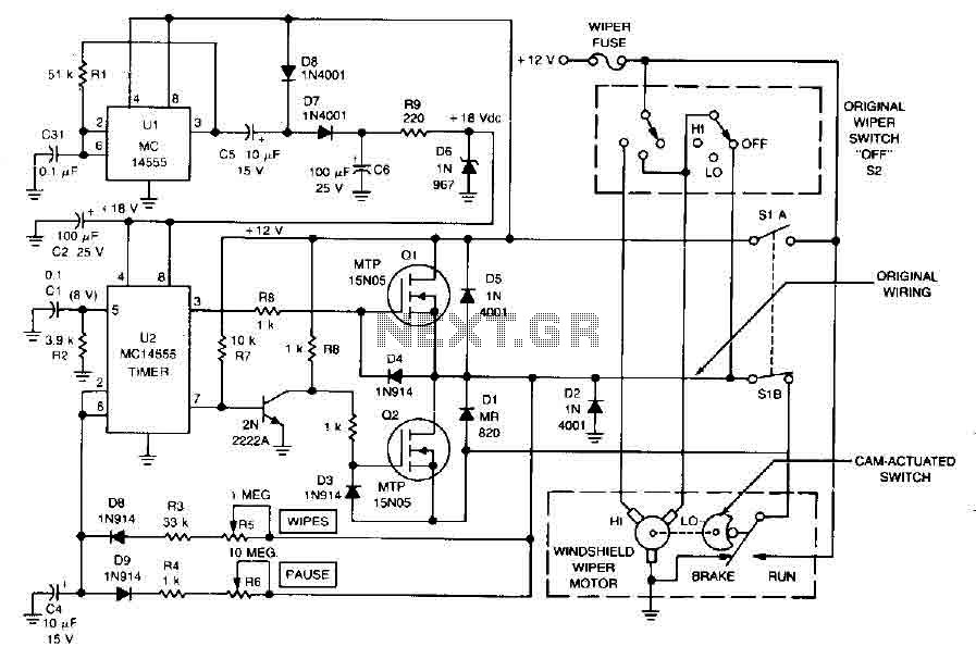
The circuit facilitates a windshield wiper delay, dynamic braking, and ensures that the windshield wipers return to their resting position. This design prevents the wiper blades from stopping at a location that could obstruct the driver's view. When the...
It is well known that simple everyday activities, such as walking on a carpet or moving in a chair, can lead to the accumulation of static charge in the body, sometimes reaching thousands of volts. This circuit is designed...
A resistor-capacitor circuit designed to prevent spark blowout. The coil's magnetic energy is converted into electrical energy stored in the capacitance C, effectively suppressing sparks and enhancing safety. The circuit is capable of functioning normally even with reverse polarity....