
TDA8571J car audio amplifier electronic project circuit design

The TDA8571J audio power amplifier is designed to deliver high-quality audio output while ensuring robust protection features and operational flexibility. The BTL configuration enhances the output power capability by allowing the amplifier to drive a load directly across the outputs of two amplifiers, effectively doubling the output voltage swing. This design is particularly advantageous in applications requiring high power output from a compact form factor.
The gain of 34 dB is significant for audio applications, providing ample amplification for various audio signals, making it suitable for car audio systems and other high-power audio applications. The low output offset voltage is critical in minimizing distortion, ensuring that the audio signal remains clean and true to the source material.
Diagnostic features such as distortion detection and short-circuit protection enable the amplifier to operate safely under various conditions, automatically shutting down or entering a safe mode if faults are detected. The temperature pre-warning feature helps prevent overheating, which could lead to damage or reduced performance.
The mode select switch allows users to toggle between operating, mute, and standby modes, providing flexibility in audio playback scenarios. Load dump protection is crucial in automotive applications, where voltage spikes can occur when the battery is disconnected while the system is still active. The amplifier's ability to remain safe under such conditions, as well as its reverse polarity protection, ensures longevity and reliability in challenging environments.
Power dissipation is minimized even in short-circuit situations, which is essential for maintaining thermal stability and preventing damage to the amplifier components. The thermal protection feature further enhances reliability by automatically reducing output when excessive heat is detected.
Overall, the TDA8571J amplifier circuit is a robust solution for high-power audio amplification, combining performance, safety, and versatility, making it an ideal choice for modern audio applications.This electronic circuit diagram is an audio power amplifier based on TDA8571J integrated circuit, class-B output amplifier with four amplifiers in a BTL configuration, each with a gain of 34 dB. Main features of the TDA8571J amplifier circuit are : high output power, low output offset voltage, diagnostic facility (distortion, short-circuit and te
mperature pre-warning), good ripple rejection, mode select switch (operating, mute and standby), load dump protection, short-circuit safe to ground and to VP and across the load, low power dissipation in any short-circuit condition, thermally protected, reverse polarity safe. This audio IC power amplifier is pin compatible with TDA8568Q audio amplifier circuit and require a 14.
4 volts power supply. 🔗 External reference
Related Circuits
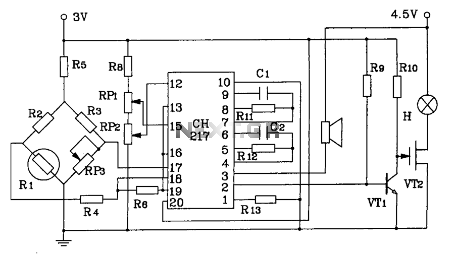
CH217 is a monolithic gas detection alarm integrated circuit. The gas detection alarm circuit diagram includes R1 as the gas sensing probe, where the resistance increases as the gas concentration decreases linearly. RP3 is used to adjust the output...
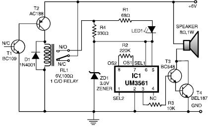
This heat detector alarm electronic project is designed using the UM3561 sound generator circuit and several common electronic components. The heat detector circuit employs a complementary pair of npn and pnp transistors to sense heat. When the temperature near...
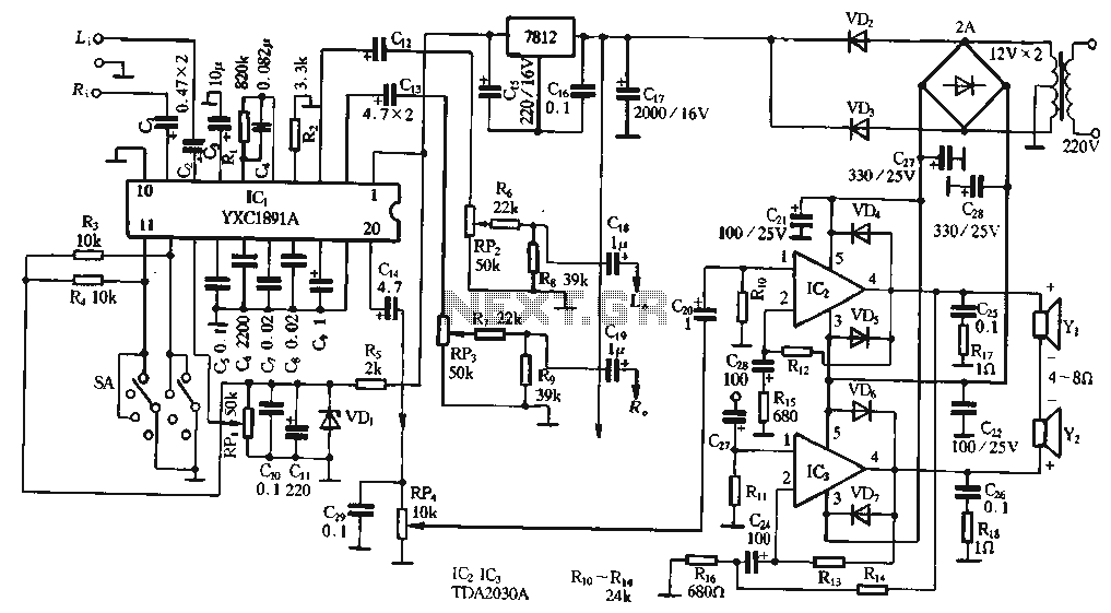
The ptPC1891A application circuit features a working state switch (SA) with a total of four options. It primarily utilizes ICs 11 and 12 to set different logical levels, as referenced in Table 5-12. The high level is denoted as...
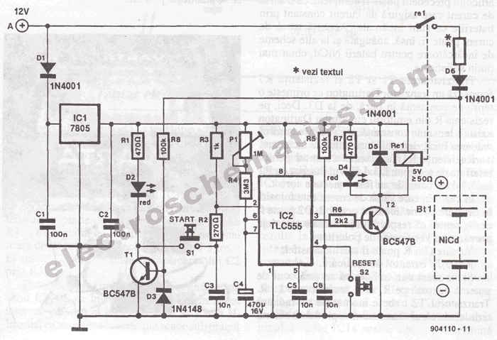
The portable battery charger has been designed to enable the charging of NiCd batteries outdoors using a 12 V vehicle battery. The portable battery charger is engineered to facilitate the charging of Nickel-Cadmium (NiCd) batteries in outdoor environments, leveraging the...
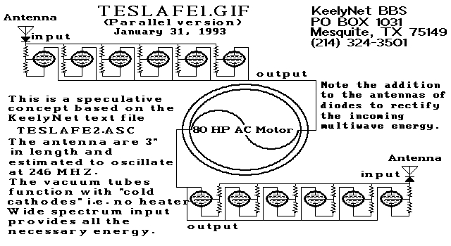
Two schematic diagrams illustrate a series and a parallel circuit configuration that Tesla may have utilized. The components featured are the 70L7GT Half Wave Rectifier tubes, which are surprisingly still available today. While there is an interest in accessing...
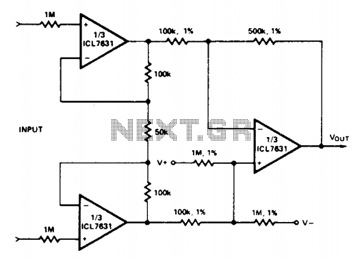
Input current (from sensors connected to the patient) is limited to less than 5 µA under fault conditions. Note that Avol = 25 single Ni-cad battery operation. The circuit is designed to ensure that the input current from patient-connected sensors...