
Car Light Dimmer 12 Volt

The circuit described is a dimming control for a dome light in an automotive application, leveraging a capacitor and an operational amplifier (op-amp) to create a gradual fade-out effect. The primary components involved in this circuit include a 22µF capacitor, an operational amplifier (specifically an IC 741), a transistor, a variable resistor (VR1), and a fixed resistor (10KΩ).
When the car door is opened, the push-to-off switch is activated, allowing the capacitor to charge to the supply voltage of 12V. The op-amp, configured as a voltage follower, ensures that the output voltage mirrors the voltage across the capacitor. This high output voltage saturates the transistor, which in turn drives the dome light to full brightness.
Upon closing the door, the switch is disengaged, and the capacitor begins to discharge through the variable resistor VR1 and the 10KΩ resistor. The discharging process results in a gradual decrease in voltage across the capacitor. Consequently, the output voltage from the op-amp also decreases, which reduces the base current to the transistor. This reduction in current results in a corresponding decrease in the brightness of the dome light, creating a smooth fade-out effect.
The circuit allows for adjustable settings via the variable resistors. VR2 is utilized to set the initial brightness of the dome light when the door is open, while VR1 controls the discharge rate of the capacitor, thereby adjusting the time it takes for the light to fade out completely after the door is closed. It is recommended to set both VR1 and VR2 to their maximum values initially to observe the full range of functionality before making precise adjustments.
Overall, this circuit enhances the aesthetic experience of the vehicle's interior lighting, providing a gradual transition that can contribute to a more pleasant ambiance during nighttime use.This unique circuit makes your dome light look cool. Usually when the car door is closed, the dome light just goes OFF. With this circuit, you can have our dome light fade slowly in brightness and finally go OFF. This slow dimming of the light gives a very good feeling at night. It looks very romantic! The circuit can be explained as follows: When the car door is open, the push to off switch of the door is ON and hence it charges the 22uF capacitor fully. The opamp is acting as a voltage follower and its output is same as the voltage across the capacitor, which is 12V when the capacitor is fully charged.
Due to a high voltage at the output of the IC, the transistor saturates, turning ON the bulb to full brightness. Now when the door is closed, the door switch is pushed in and hence the switch goes OFF. When the switch is OFF, the capacitor starts discharging slowly through VR1 and the 10K resistor and the voltage across it decreases slowly. Hence at the output of IC 741 also the voltage decreases gradually, hence decreasing the base current to the transistor.
This produces a slowly decreasing current through the bulb and the bulb fades out and finally when the capacitor is fully discharged, the bulb goes OFF. After building the circuit, with the push-to-off switch in ON position (not pushed in) i.e. the car door open, adjust the preset VR2 to the required initial brightness of the bulb. Then push the switch in to turn it OFF(or close the door) and adjust VR1 for the time to bring the bulb from full brightness to OFF.
I would suggest you set VR1 and VR2 to their maximum values. 🔗 External reference
Related Circuits
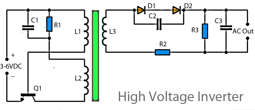
This inverter circuit operates using a transistor and transformer, along with other components, to elevate the voltage. The input supply voltage ranges from 3V to 6V DC, which is then converted to a high voltage AC output. However, the...
The circuit presented is an integrated circuit (IC) controlled emergency light. Its key features include automatic activation of the light during mains failure and a battery charger equipped with overcharge protection. In the absence of mains power, relay RL2...
This circuit utilizes a 13-volt zener diode, D2, which is responsible for voltage regulation. Approximately 0.7 volts are dropped across the base-emitter junction of the transistors, resulting in a higher current output of 12.3 volts. The circuit is capable...
The addition and subtraction functions of an operational amplifier are facilitated through an external feedback network, which places the integrated operational amplifier in a deep state of negative feedback. In this linear region, the relationship between input and output...

A high-input-resistance operational amplifier (op-amp), a bridge rectifier, a microammeter, and several discrete components are necessary to implement this versatile circuit. This circuit can measure DC, AC RMS, AC peak, or AC peak-to-peak voltage by simply altering the resistor...
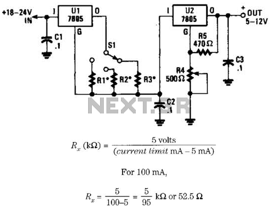
This voltage regulator and current limiter combination can be constructed using two 7805 regulators as illustrated. Resistors R1, R2, and R3 should be chosen to achieve a 5-V drop at the maximum allowable current limit. Switch S1 selects one...