
Combination Voltage And Current Regulator Circuit

This circuit utilizes two 7805 voltage regulators to create a voltage regulation and current limiting system. The 7805 is a popular linear voltage regulator that outputs a stable 5V, making it suitable for various electronic applications. In this configuration, the two regulators work together to provide both voltage regulation and the ability to limit the current flowing through the circuit.
The resistors R1, R2, and R3 play a crucial role in setting the current limit. The selection of these resistors must ensure that when the maximum current is drawn, the voltage drop across them is precisely 5V. The values of these resistors can be calculated based on Ohm's Law, taking into consideration the maximum allowable current for the specific application. The switch S1 allows the user to select between three different current limits, providing flexibility in the operation of the circuit.
It is essential to account for the current consumption of the voltage regulator itself. In this case, the regulator U1 requires a minimum of 5 mA to function correctly. Consequently, the design must ensure that the minimum current limit setting is at least 10 mA or higher to maintain proper operation. This requirement is satisfied by using a resistor value of R1 equal to 1.25 kΩ, which can be adjusted based on the desired current limits.
The overall design should include proper heatsinking for the 7805 regulators, as they may dissipate significant power when operating near their maximum current limits. Additionally, bypass capacitors should be placed close to the input and output terminals of the regulators to ensure stable operation and reduce noise in the output voltage.
In summary, this circuit provides a reliable solution for applications requiring both voltage regulation at 5V and the capability to limit current to protect downstream components from excessive current flow. Proper selection of resistors and consideration of the regulator's operational requirements are critical to achieving optimal performance. This voltage-regulator/cuiTent-liimter combination can be made from two 7805 regulators as shown. Rl, R2, and R3 shouldbe selected for a 5-V drop at the maximum allowable currant limit. SI selects one of the three current values. Do not forget that Ul requires 5 mA to operate and this means that the minimum current limit setting should be 10 mA or more (Rl - 1.25 kQ). Resistor values are as shown.
Related Circuits
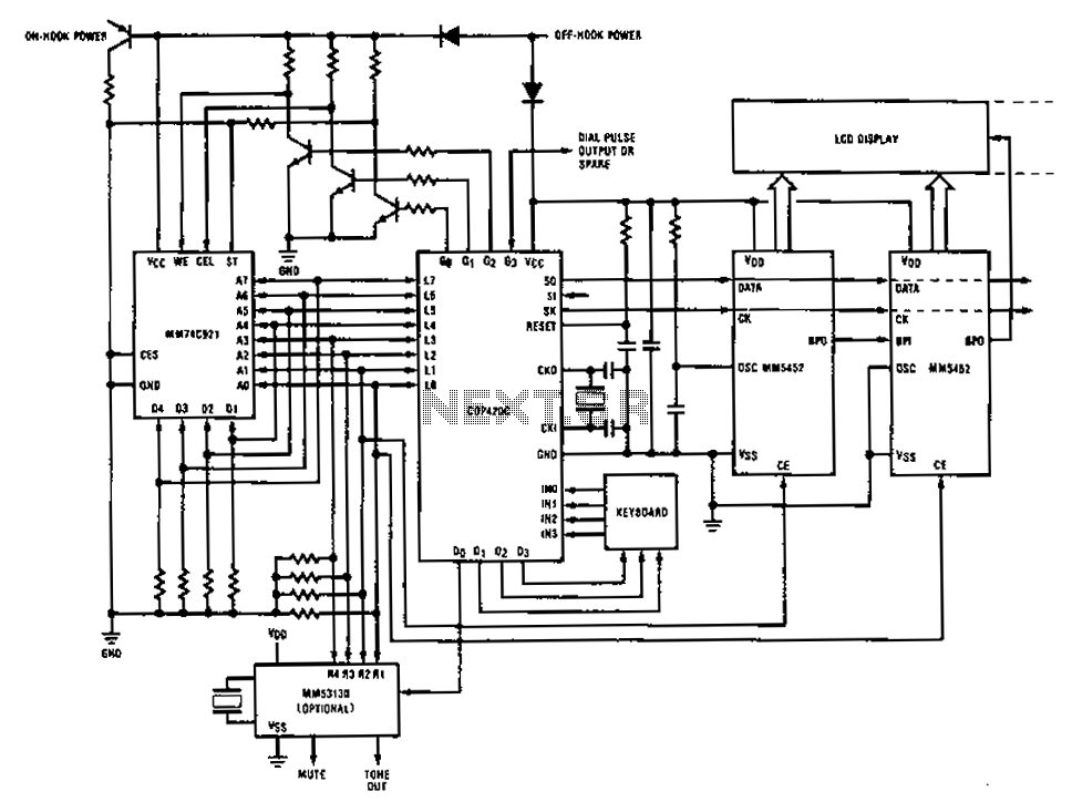
A compilation of dial phone numbers, including 15 commonly used libraries and the dialed number, is stored in standard CMOS RAM. A single-button keypad facilitates the input of a phone number, which can be dialed directly or stored in...
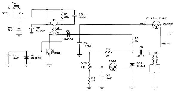
Caution! This strobe light circuit operates on 220V, making measurements and experiments extremely hazardous, even after disconnecting it from the mains. The strobe light circuit is designed to produce high-intensity flashes of light at specified intervals. It typically consists...
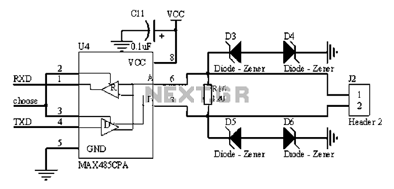
The RS485 bus is a widely used serial bus standard that employs balanced differential transmission and reception techniques, enabling it to effectively suppress common mode interference. It is particularly advantageous for communication distances ranging from tens of meters to...
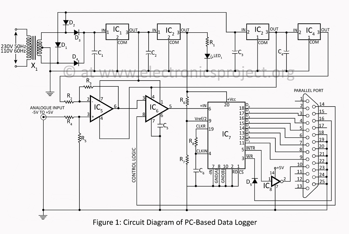
A PC-based data logger utilized in physics laboratories for automating simple experiments and monitoring slowly varying physical variables across various PC-based projects. The PC-based data logger serves as an essential tool in physics laboratories, enabling the automation of experiments and...
This project was a surprise as the BC547 transistor (equivalent to 2N2222) can be used to construct a 500mW linear amplifier that operates across the entire HF band with excellent spectral purity and without the need for neutralization. The...
Many analog ohm meters have a non-linear scale, which results in poorer resolution at higher resistance values. This is due to the use of inexpensive current sources. Many analog ohm meters operate on a principle where the scale is not...