
CAR RADIO WITHOUT ANTENNA

The car radio without an antenna represents a significant advancement in automotive audio technology. The design focuses on integrating an FM booster that enhances reception capabilities, allowing users to access a wider range of FM stations without the traditional external antenna. The use of the 2SC2570 transistor in the common-emitter configuration is critical for achieving the necessary gain to ensure clarity and quality of the audio output, particularly for distant stations.
The internal antenna, a key component of this design, is strategically placed within the vehicle to maximize signal reception while maintaining aesthetic appeal. The design must consider the vehicle's structure and materials, which can affect signal propagation. The low-noise amplifier (LNA) plays a vital role in minimizing the noise that can accompany weak signals, thereby improving overall sound quality.
The project also emphasizes the importance of component selection, particularly resistors and capacitors, which are fundamental in establishing the desired circuit characteristics. The trimmer capacitors are essential for fine-tuning the circuit, ensuring optimal performance during operation. The careful calibration of these components is necessary to achieve the best possible reception and audio fidelity.
In conclusion, the development of a car radio without an external antenna not only addresses practical issues related to aesthetics and functionality but also showcases the evolution of radio technology. By leveraging advancements in semiconductor technology and circuit design, this project aims to deliver a modern solution for automotive audio systems, enhancing the driving experience while embracing the latest innovations in technology.In the present era, the various technologies we can see. On average, every three months there is a new technology. So not supprisingly, with so many unique and innovative equipment trigerred. Car`s radio without antenna are our project. This is an idea from development of handphone. We can see the development of handphone from the radiophones have a long and varied history going back to Reginald Fessenden `s invention and shore-to-ship demonstration of radio telephony, through the Second World War with military use of radio telephony links and civil services in the 1950s until now. So we want to create the new development of radio that do not use the external antenna. Furthermore, it can solving the problem for radio too. In this proposal, discusses the design and circuit design of this tool. Car`s radio without antenna This radio`s car without antenna functioning by using three main content which are FM booster, internal antenna and the original circuit of radio without the antenna.
There are content of this project: FM boosterthat can be used to listen programs from distant FM stations clearly. The circuit comprises a common-emitter tuned RF preamplifier wired around VHF/UHF transistor 2SC2570 ( C2570).
We will connect the internal antenna to the booster and go to RF. Then the LNA will boost the signal one more time. Its mean the signal will be boosting twice. So we can get the great frequency. In this chapter we will describe the project components are used, the flow of projects, operation of the circuit, and software programs are used together with a block diagram of the entire project. The resistor is a component that limits the current flow. Resistor selection is made according to its suitability for use in the circuit. When selecting resistors, four in the table below should be considered. Fixed resistor is the resistor resistance value is not changeable. However, factors such as changes in temperature, the material may flow resistor or the resistance to change remains.
The resistance can be specified by color code or a printed card. The resistance of a resistor can be determined by interpreting the color lines are printed on the body. Usually there are four lines are printed on the resistor body. The first and second strip shows the first digit and second digit. The third path is the value of the multiplier. The fourth path is tolerance. Interpretation by the code set is shown in Table 3. 2. In this project we use several types of resistors. For our power supply circuit using a 470 © resistor value of 1K and while the circuit is "relay card" we use a resistor value is 39 © for the circuit and PIC (Micro Program Controller) is valued resistors 50 © and 500 ©.
Figure 2. 1 shows examples of resistors used in the circuit. Capacitors are components that store electrical charges. Basically, a capacitor consists of two metal plates, or two parallel conductors separated by an insulator called a dielectric. This dielectric may comprise air, paper, mica, polyester or electrolytic. Figure 2. 2 shows the construction of a capacitor. Capacitor in the circuit function is to store charge temporarily, and it can be charged and discharged.
Figure 3. 3 shows the type of capacitor used in the circuit PIC (Micro Program Controller). Trimmer capacitors (trimmers) are miniature variable capacitors. They are designed to be mounted directly onto the circuit board and adjusted only when the circuit is built. A small screwdriver or similar tool is required to adjust trimmers. The process of adjusting them requires patience because the presence of your hand and the tool will slightly change the capacitance of the circuit in the region of the trimmer!
Trimmer capacitors are only available with very small capacitances, normally less than 100pF. It is impossible to reduce their capacitance to zero, so they are usually specified by their minimum and maximum values, for example 2-10pF. This type of variable capacitor (a trimmer) is operated with a small screwdriver or similar tool. It is designed to be set when the circuit is made and then left without further adjustment. To calibrate this circuit you need to adjust input/output trimmers (VC1/VC2) for maximum gain. An inductor is simply a coil of insulated wire. The strength of its inductance depends on several factors, including how many turns of wire are in the coil, and whether the coil surrounds an iron core.
A coil of wire which creates a magnetic field when current passes through it. It may have an iron core inside the coil. It can be used as a transducer converting electrical energy to mechanical energy by pulling on something. Simple circuits made of an inductor, capacitor and resistor can enhance a particular signal frequency.
For example, a radio uses this circuit to tune in different stations. An inductor on its own can filter out frequencies that are higher or lower than the one it`s tuned to. Two inductors, placed closely together, make up a transformer. A transformer can isolate unwanted direct current (DC) signals, or increase or decrease the voltage in an alternating current (AC) signal.
Transformers reduce wire losses for electrical power distribution, making electricity more affordable. The same inductor circuits used to amplify existing signals can also be used to generate new ones. A circuit that does this is called an oscillator, and it is used to broadcast television and radio channels at millions of cycles per second.
Simple inductor circuits, called chokes or traps, eliminate interfering frequencies from radio and television signals. For example, you can use a choke to keep a nearby police radio transmission from getting into your normal radio channels.
A solenoid is an electromechanical device consisting of an inductor and a spring-loaded iron core. When you put a DC current through a solenoid, the inductor pulls the core inside. The iron core, when connected to other parts of a machine, can act as an electrically-activated gate or trigger. Atransistoris a semiconductor device used to amplify and switch electronic signals and power. It is composed of a semiconductor material with at least three terminals for connection to an external circuit.
A voltage or current applied to one pair of the transistor`s terminals changes the current flowing through another pair of terminals. Because the controlled (output) power can be much more than the controlling (input) power, a transistor can amplify a signal.
Today, some transistors are packaged individually, but many more are found embedded in integrated circuits. The transistor is the fundamental building block of modern electronic devices, and is ubiquitous in modern electronic systems.
Following its release in the early 1950s the transistor revolutionized the field of electronics, and paved the way for smaller and cheaper radios, calculators, and computers, among other things. There are two types of transistors, which have slight differences in how they are used in a circuit. Abipolar transistorhas terminals labeledbase, collector, andemitter. A small current at the base terminal (that is, flowing from the base to the emitter) can control or switch a much larger current between the collector and emitter terminals.
For afield-effect transistor, the terminals are labeledgate, source, anddrain, and a voltage at the gate can control a current between source and drain. The image to the right represents a typical bipolar transistor in a circuit. Charge will flow between emitter and collector terminals depending on the current in the base. Since internally the base and emitter connections behave like a semiconductor diode, a voltage drop develops between base and emitter while the base current exists.
The amount of this voltage depends on the material the transistor is made from, and is referred to asVBE. Transistors are commonly used as electronic switches, both for high-power applications such as switched-mode power supplies and for low-power applications such as logic gates.
In a grounded-emitter transistor circuit, such as the light-switch circuit shown, as the base voltage rises, the base and collector current rise exponentially. The collector voltage drops because of the collector load resistance (in this example, the resistance of the light bulb).
If the collector voltage were zero, the collector current would be limited only by the light bulb resistance and the supply voltage. The transistor is then said to besaturated- it will have a very small voltage from collector to emitter.
Providing sufficient base drive current is a key problem in the use of bipolar transistors as switches. The transistor provides current gain, allowing a relatively large current in the collector to be switched by a much smaller current into the base terminal.
The ratio of these currents varies depending on the type of transistor, and even for a particular type, varies depending on the collector current. In the example light-switch circuit shown, the resistor is chosen to provide enough base current to ensure the transistor will be saturated.
In any switching circuit, values of input voltage would be chosen such that the output is either completely off, [21] or completely on. The transistor is acting as a switch, and this type of operation is common in digital circuits where only "on" and "off" values are relevant.
The common-emitter amplifier is designed so that a small change in voltage (Vin) changes the small current through the base of the transistor; the transistor`s current amplification combined with the properties of the circuit mean that small swings inVinproduce large changes inVout. From mobile phones to televisions, vast numbers of products include amplifiers for sound reproduction, radio transmission, and signal processing.
The first discrete transistor audio amplifiers barely supplied a few hundred milliwatts, but power and audio fidelity gradually increased as better transistors became available and amplifier architecture evolved. 🔗 External reference
Related Circuits
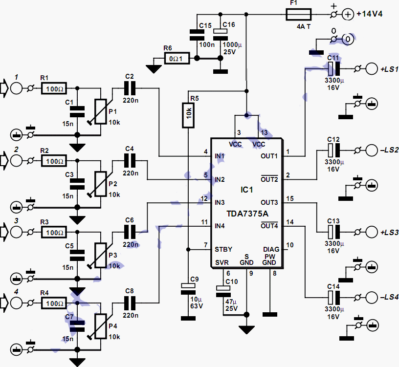
This quad amplifier is designed primarily for automotive use but can also be applied in various medium-power scenarios. The TDA7375A is suitable for situations requiring a reasonable amount of audio power with a relatively low supply voltage. It is...
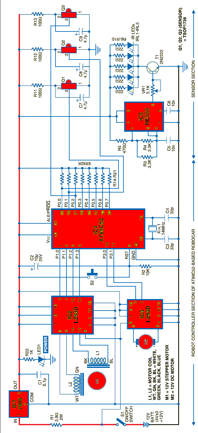
A robot can be defined as an electro-mechanical system with the capability of sensing its environment, manipulating it, and acting according to a preprogrammed sequence. It is a machine that... Robots are complex systems that integrate various components to perform tasks...
A common car inverter circuit and its working principle. Car inverter specifications include: Input voltage: DC 10V to 14.5V; Output voltage: AC 200V to 220V with a tolerance of 10%; Output frequency: 50Hz with a tolerance of 5%; Output...

Frequency shift keying (FSK) is a widely used digital modulation technique for data transmission. Common applications of FSK modulation encompass both wired and wireless data transmission, as well as infrared remote controls for consumer electronic devices. FSK demodulation can...
PARTS LIST C1 0.22 µF (224) C2 22nF (223) C3 10nF (103) C4 27pF C5 22pF C6 3.3nF (332) C7 180pF (181) C8 330pF (331) C9 3.3nF (332) C10 150pF (151) C11 82pF C12 68pF C13 220pF (221) C14...
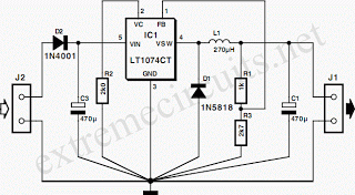
This circuit utilizes the LT1074CT switching regulator integrated circuit (IC). For a more comprehensive explanation of the design, it is recommended to refer to Application Note AN35 published by Linear Technology. The schematic illustrates the LT1074CT functioning as a...