
TDA7000 FM Radio Receiver Circuit

This circuit is designed around the TDA7000 integrated circuit, which is a low-voltage FM radio receiver. The components listed include various capacitors, resistors, and inductors that form the necessary tuning and filtering stages of the receiver.
The capacitors (C1 to C19) serve different roles, such as coupling, decoupling, and tuning. For instance, C1 (0.22 µF) and C14 (100nF) are likely used for decoupling the power supply to ensure stable operation of the TDA7000. The tuning capacitor VC1, with a range of 15-30pF, is critical for adjusting the frequency of the FM signal being received.
The resistors R1 (10kΩ), R2 (22kΩ), and R3 (10kΩ) are used to set biasing and gain levels within the circuit. Their values are chosen based on the requirements of the TDA7000 to achieve optimal performance.
The inductors L1 and L2 are constructed from 23 SWG enamelled copper wire, wound on a 3mm diameter form. L1, with approximately 78nH inductance, functions as the tuning coil, while L2, with approximately 70nH, serves as the antenna coil. The close-wound configuration of these coils enhances their performance at the desired frequency range of 1.5 to 110 MHz.
The circuit also includes a mute switch (S1) that disables the mute function when engaged, allowing audio output during operation. The use of a telescopic antenna or a 1m wire as the antenna input ensures good reception of FM signals.
The TDA7000 requires a supply voltage between 2.7V and 10V, with a typical supply current of 8mA at 4.5V. This low power requirement makes it suitable for battery-operated applications. The circuit's sensitivity for -3 dB limiting indicates its capability to maintain audio quality even at lower signal strengths, which is crucial for FM reception.
Overall, this schematic provides a comprehensive overview of an FM receiver design utilizing the TDA7000, with careful consideration of component selection and circuit configuration to optimize performance.PARTS LIST C1 0. 22 µF (224) C2 22nF (223) C3 10nF (103) C4 27pF C5 22pF C6 3. 3nF (332) C7 180pF (181) C8 330pF (331) C9 3. 3nF (332) C10 150pF (151) C11 82pF C12 68pF C13 220pF (221) C14 100nF (104) C15 330pF (331) C16 220pF (221) C17 1. 5nF (152) C18 470nF (474) C19 100nF (104) VC1 FM Tuning Capacitor (15-30pF) R1 10k © R2 22k © R3 10k © L1 5 (5.
75) Turns of 23 swg enamelled copper wire close-wound on a 3mm diameter. (‰ 78nH) L2 4 (4. 75) Turns of 23 swg enamelled copper wire close-wound on a 3mm diameter. (‰ 70nH) IC1 TDA7000 ANT Telescopic antenna or 1m wire S1 Mute Switch (mute is disabled when switch is on. ) L1:Tuning Coil, 5 (5. 75) Turns of 23 swg enamelled copper wire close-wound on a 3mm diameter. L2: Antenna Coil, 4 (4. 75) Turns of 23 swg enamelled copper wire close-wound on a 3mm diameter. TDA7000 QUICK REFERENCE DATA Supply voltage range (pin 5) VP 2. 7 to 10 V Supply current at VP = 4. 5 V IP typ. 8 mA R. F. input frequency range frf 1. 5 to 110 MHz Sensitivity for -3 dB limiting 🔗 External reference
Related Circuits
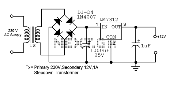
This is a straightforward 12V power supply circuit diagram. It features a fixed voltage output and is based on the LM7812 voltage regulator integrated circuit. The 12V power supply circuit utilizing the LM7812 voltage regulator is designed to provide a...
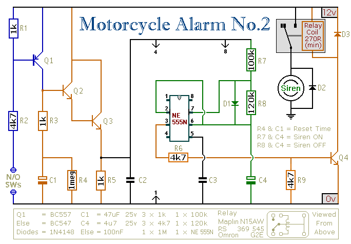
This circuit provides an intermittent siren output with an automatic reset function. It can be manually activated using a key switch or a concealed switch, and it can also be configured to engage automatically when the ignition is turned...
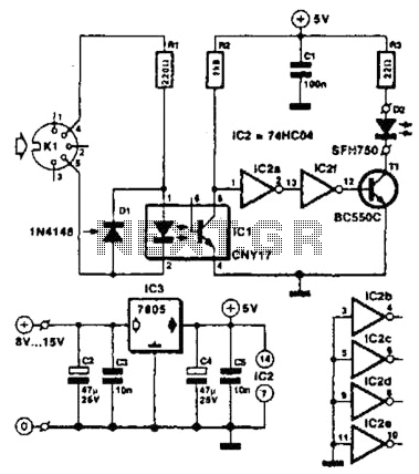
Used for digital control of musical instruments, this transmitter converts digital data signals into equivalent optical signals for a fiber optic cable interface. Optocoupler IC1 provides isolation, driving IC2-a and -b, and T1, ultimately providing a cable driver LED...
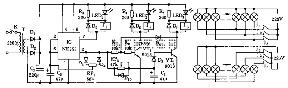
The controller features a buck rectifier circuit utilizing a 555 multivibrator, designed for controlling approximately 220V, 5W low-power parallel lights or 6 to 12V small bulb series. The 555 timer, along with components D3, D4, RP1, and C2, forms...
It is the essential continuity of circuits Sel 8 Sources and Up/Down Sel 8 Sources, but can work and autonomously, collaborating with any suitable circuit of control. The Relay 1-8 can be 6-24v DC. For current of collector of...
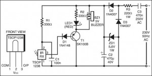
The following circuit illustrates an IR Remote Control Tester Circuit. Features include that transistor T1 conducts during the negative pulse period, and there is a data output pin. The IR Remote Control Tester Circuit is designed to verify the functionality...