
Car Reversing Horn With Flasher

The described circuit employs a dual timer IC, specifically the NE556, which is a versatile component commonly used in timing applications. In this configuration, the NE556 is set up to detect the reverse gear activation of a vehicle. When the car is shifted into reverse, a signal is sent to the NE556, triggering it to generate a tone or beep through the car's horn.
The circuit typically includes a few additional components to ensure proper operation. A power supply, often sourced from the vehicle's battery, provides the necessary voltage to the NE556. Resistors and capacitors are used in conjunction with the timer to define the timing intervals and the frequency of the output signal, which can be adjusted to achieve the desired sound characteristics of the horn.
Input from the vehicle’s reverse light switch can be connected to the trigger pin of the NE556. This input ensures that the circuit is only activated when the vehicle is indeed in reverse, preventing accidental horn activation. The output from the NE556 can be connected to a relay, which in turn activates the car horn, allowing for higher current flow than the timer IC can handle directly.
In summary, this circuit provides a practical solution for alerting pedestrians and other drivers when a vehicle is in reverse, enhancing safety through audible warnings. The use of the NE556 timer makes the circuit reliable and efficient, suitable for automotive applications.Here is a simple circuit that starts playing the car horn whenever your car is in reverse gear. The circuit (1) employs dual timer NE556 to generate the s.. 🔗 External reference
Related Circuits

This circuit utilizes a voltage-doubler supply to charge a 60 µF capacitor and subsequently discharges it through a Xenon lamp. The SIDAC device, produced by Motorola, is a two-terminal device that triggers at a predetermined voltage. The components R4,...
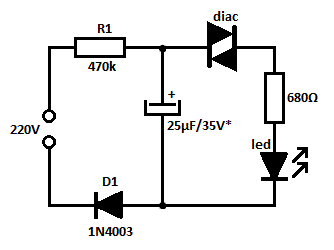
This is likely the simplest concept for generating a flashing light from an LED using alternating current (AC). The circuit provides a straightforward method for flashing one or more LEDs using high-voltage direct current (DC) sourced from mains electricity....

Here is a Simple Circuit to give a Flashing LED, With a "Rising and Falling" Brightness. It Uses the Sawtooth waveform from pins 2 and 6 to create the rise and fall. The Resistor and LED on Pin 3...

This is the complete wiring diagram for the 1997 Honda CR-V. It includes wiring diagrams for each electrical module of the Honda CR-V, such as the Rear Wiper/Washer Circuit, Front Wiper/Washer Circuit, Warning System Circuits, and the Supplemental Restraint...

In the video system shown in Figs. A and R, a single coaxial cable transmits power to a remote location, selects one of eight video channels, and returns the chosen signal. This system can select from multiple remote surveillance...
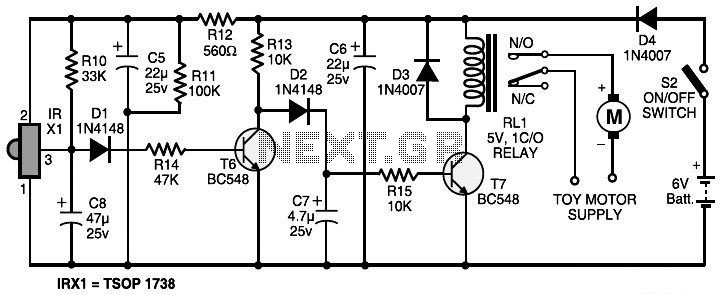
The circuit features an infrared transmitter-receiver pair that uses infrared beam transmission to turn the toy car on or off. It is designed for simple operation, with potential modifications to enable the toy car to turn left or right....