
diac controlled led flasher 3

The circuit design described utilizes a straightforward approach to create a flashing LED effect. The key component, the diac, operates as a switch that allows current to flow once the voltage exceeds its threshold, thus controlling the LED's illumination. The inclusion of diode D1 ensures that the alternating current is converted into a usable direct current, which is essential for the operation of the diac and LED. Resistor R1 is critical for limiting the current flowing into the diac, preventing damage and ensuring reliable operation. Resistor R2 serves to further protect the LED by restricting the current to a safe level, preventing potential burnout.
The capacitor C1 plays a vital role in determining the flashing frequency of the LED. By adjusting its capacitance, one can control how quickly the LED turns on and off. This feature allows for customization of the flashing effect, making it suitable for various applications, such as decorative lighting or indicators. The circuit's simplicity makes it an excellent choice for educational purposes, demonstrating fundamental concepts in electronics such as rectification, capacitive charging, and the operation of diacs.
Safety precautions are paramount given the high-voltage nature of the circuit. Proper insulation and housing are necessary to prevent accidental contact with live components. Additionally, the circuit should be tested and operated in a controlled environment to mitigate risks associated with high voltage. Overall, this circuit exemplifies a practical application of basic electronic components to achieve a visually engaging outcome while highlighting essential safety considerations.This is probably the simplest idea to generate flashing light from an LED using AC. The circuit is relatively the simple way of flashing one or more LEDs from a high voltage DC obtained from Mains. This can be used as a Mains indicator or Mock flasher. The circuit uses a diac for the alternate switching of LED. The diac is usually used in pulse ge nerator circuits to trigger SCR and Triac. If a low voltage passes through a diac, it simply behaves like an open circuit and only very low current passes through it. But if the voltage increases to the breakdown threshold of the diac, it will pass heavy current. Usually 35 volt DC is required to attain the threshold level of diac. Unlike SCR, diac conduct in both the directions. In the circuit, a commonly available DB3 diac is used. Diode D1 rectifies AC and generates a high volt DC. Resistor R1 safely controls the DC to operate diac and LED. Normally LED will be OFF. When the capacitor charges fully, diac gets the threshold voltage and fires. This provides current to LED and it lights. Resistor R2 makes the LED current to a safer value of 30 mA. When the diac conducts, C1 discharges and again the breakdown voltage of diac decreases and LED turns off.
Thus the charging/discharging cycles of C1 makes the LED flashing. The value of C1 determines the flash rate. Higher values give slow flash rate and vice versa. If the threshold level of diac is not obtained using the given value of R1, reduce it to 10K, but its wattage should be increased to 5 watts. Caution The circuit is directly connected to high volt AC and there is no galvanic isolation. Take utmost care while handling the circuit. Enclose it in a shock proof case. Do not touch any points when it is connected to Mains. 🔗 External reference
Related Circuits
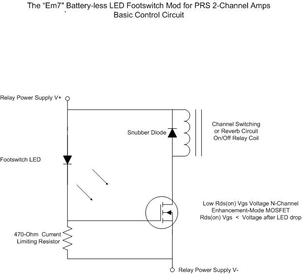
For individuals seeking LED-based footswitching without the inconvenience of battery installation, a battery-less LED-based footswitch modification is being developed for 2-channel amplifiers. This solution is designed to work with the existing TRS jack and footswitch, and it will involve...

PIC controlled 500W Modified Sine Wave Inverter. The PIC16F628A is programmed to produce a logic 5V signal for 5ms at pin 17, followed by 15ms off. The described circuit implements a 500W modified sine wave inverter controlled by a PIC16F628A...

This circuit diagram represents a radio-controlled system, commonly utilized in toy car applications for children. The circuit comprises two main components: the transmitter and the receiver circuits. The transmitter circuit generates radio signals through an oscillator circuit built with...
The control voltage is fed into the first half of a 1458 op-amp, this stage inverts the signal and sets the offset and gain for the right channel gain control circuit. This signal is then fed into the second...

This circuit gives the sense of movement of a ball up and down, after the LEDs turn on successively, one after the other. As soon as it reaches one end or the other, it makes the opposite movement back....

The RF engineer often needs an instrument that can reliably and quickly test a low-frequency quartz crystal unit. However, such equipment is challenging to find, and engineers frequently consult electronic circuit handbooks for schematics that can accomplish this task....