
Video Signal Carrier Circuit

The described video system utilizes a coaxial cable as a versatile medium for both power supply and video signal transmission. The 8-channel multiplexer allows for the selection of one of eight different video sources, such as surveillance cameras, enabling flexible monitoring options. The multiplexer, integrated with an amplifier, enhances the video signal strength, ensuring that it remains clear and strong over the distance traveled through the coaxial cable.
The coupling of the multiplexer’s output to the coaxial cable is achieved through capacitor C1, which serves to block any DC components while allowing the AC video signal to pass through effectively. This is crucial for maintaining signal integrity, as any DC offset could distort the video signal. On the other hand, inductor L1 acts as a decoupling element, filtering out unwanted high-frequency noise that may be present in the video signal, thus further ensuring the quality of the transmitted video.
The design of this system is particularly advantageous in applications requiring remote video monitoring, as it simplifies installation by reducing the number of cables needed. The use of a single coaxial cable streamlines the setup, reduces potential points of failure, and minimizes installation time and costs. Overall, this system exemplifies an efficient approach to video signal management in surveillance applications.In the video system of Figs. A and R, a single coaxial cable carries power to the remote location, selects one of eight video channels, and returns the selected signal. The system can choose one of several remote surveillance-camera signals, for example, and display the picture on a monitor near the interface box.
The heart of the multiplexer box (A) is a combination 8-channel multiplexer and amplifier(IC1). Cll couples the multiplexer`s baseband video output to the coax, and LI decouples the vi. 🔗 External reference
Related Circuits
It is easy to miss the sound of a doorbell while watching TV. This circuit addresses the issue by providing a visual indication, such as a lamp or an LED. Connecting a lamp directly in parallel with the doorbell...
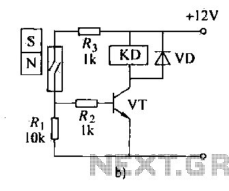
The automatic weapon features a magnetic switch circuit that is simple, reliable, has a low failure rate, and offers good versatility. It can be used to output performance or convert mechanical displacement. The circuit diagram utilizes a Hall switch...
This circuit is a simple IR detector for testing IR remote controllers. The circuit is based on one phototransistor which receives the IR beam. The NPN transistor works as an amplifier which feeds current to the LED. When this...

This solid-state Tesla Coil design is similar to the two-transistor version available on this site, utilizing a standard flyback transformer to generate high voltage output. Unlike the previous design, it employs a 555 timer to effectively drive a single...
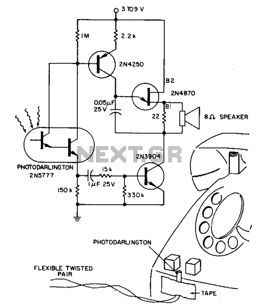
A 2N5777 photo-Darlington cell detects blinking light from transparent plastic buttons. A high-gain 2N3904 transistor is used to switch the power ON and OFF. The circuit can remain continuously connected to a 9 V battery, drawing less than a...

The LM2917 IC chip is specifically designed as a Frequency to Voltage Converter. It requires only a few external components for its operation. The datasheet for the LM2917 IC includes several application examples of the Frequency to Voltage Converter....