
Simplest RF Transmitter circuit diagram

The circuit operates as a basic radio transmitter, utilizing a few fundamental components that work together to generate and modulate radio frequency signals. The core of the circuit includes a transistor (Q1), which acts as the amplifying element. The transistor is biased correctly to allow it to operate in its active region, enabling it to amplify the input signal.
The inductor (L1) plays a crucial role in determining the frequency of the transmitted signal. By adjusting the number of turns in the coil or changing the diameter of the coil form, the inductance can be modified. This, combined with the capacitive element (C1), forms a resonant LC circuit, where the frequency of oscillation can be calculated using the formula \( f = \frac{1}{2\pi\sqrt{LC}} \). This relationship highlights the importance of both L1 and C1 in tuning the transmitter to the desired frequency.
The resistor (R1) and the optional thermistor or photoresistor introduce variability into the circuit, allowing for dynamic control of the output frequency based on environmental conditions such as temperature or light levels. This feature can be particularly useful in educational projects where demonstrating the principles of radio frequency transmission and modulation is the goal.
The power supply, ranging from 1.5 to 3 volts, should be chosen based on the availability of batteries and the desired operating time of the transmitter. The use of hearing aid batteries or lithium coin cells is recommended due to their compact size and adequate voltage output for the circuit's requirements.
Overall, this simple radio transmitter circuit provides an excellent platform for experimentation and learning, allowing users to explore the fundamentals of radio transmission and the impact of various component values on circuit performance.This is probably the simplest radio transmitter that you will find anywhere. It has a total of five parts and can be constructed into a very small space. It is great for science fair projects or other science related projects where short range transmission is useful. It runs on 1. 5 to 3 Volts, with small hearing aid batteries or lithium coin ce lls being ideal. A thermistor or photoresistor can be inserted in series with R1 to have a varying output frequency dependent on the input. The frequency can also be changed by changing the value of C1. A 2N2222 transistor is recommended, but you can try other types also. Performance tends to vary from type to type as well as from transistor to transistor. L1 is 20 to 30 turns of thin magnet wire (24 to 32 ga. ) close wound around a 1/8 to 1/4 ³ diameter non-conductive form. The coil is tapped 1/3 of the way from one end and the tap connected to the emitter of Q1. Experiment with all of the values in this circuit. Nothing is critical, but performance can be varied considerably. 🔗 External reference
Related Circuits
The liquid level controller circuit comprises a power supply circuit and a level detection control circuit, as illustrated in the accompanying chart. The power supply circuit includes a power switch (S1), a power transformer (T), bridge rectifiers (UR1, UR2),...
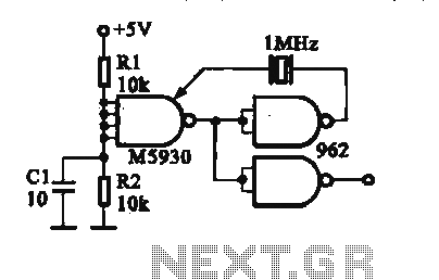
A crystal oscillator is implemented using a DTL (Diode-Transistor Logic) integrated circuit. The oscillation frequencies are 100 kHz and 1 MHz. The circuit consists of a gate circuit that generates a signal for the oscillator circuitry in DTL. The crystal...

A simple infrared-controlled switch can be operated using a TV remote control. The load can be any AC-powered device connected to the relay. The load activates for three minutes before turning off and can be used to switch on...
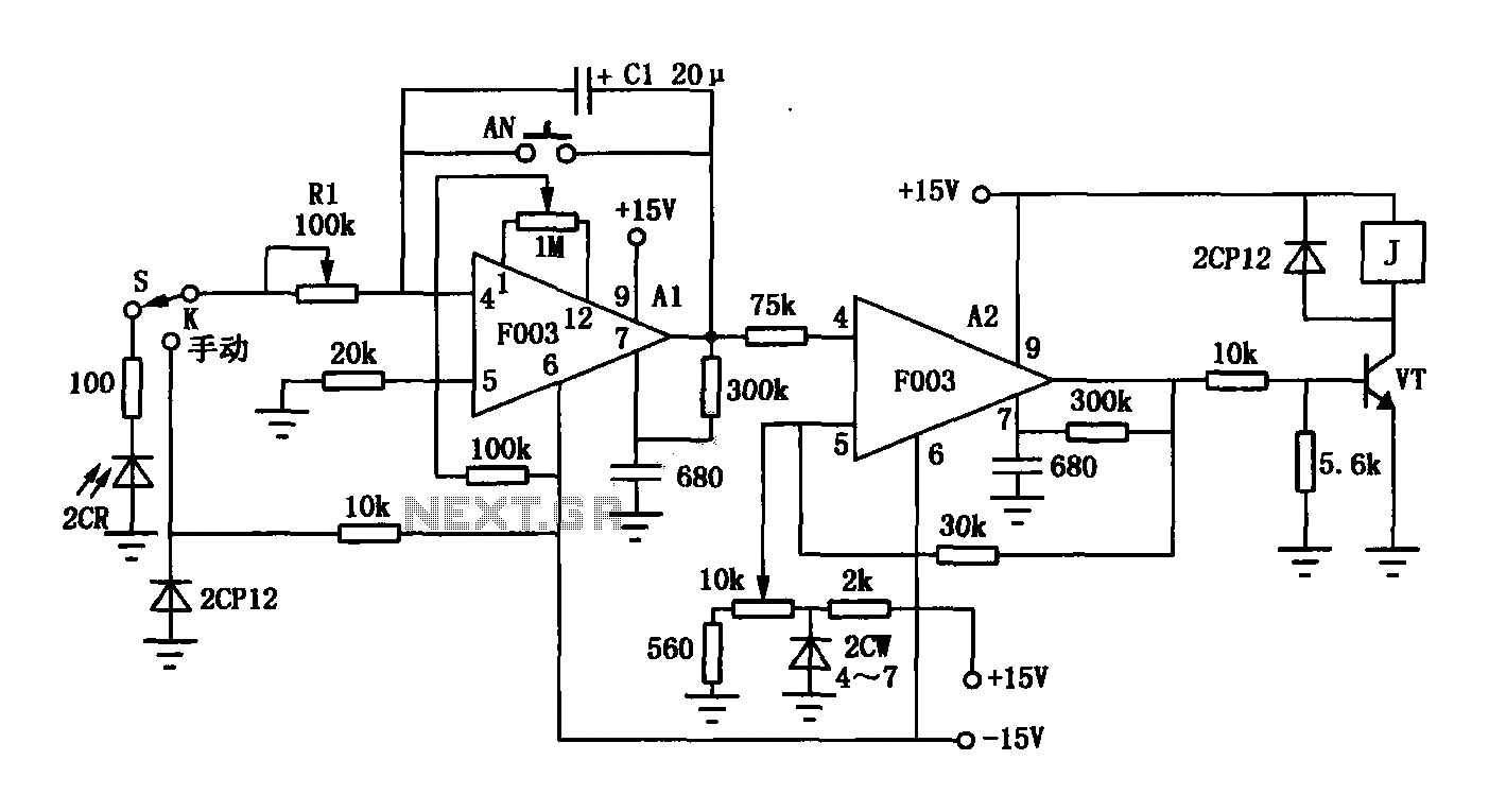
The F003 circuit is a versatile photographic component that functions as an operational amplifier amplifying automatic timer circuit. The operational amplifier A1 serves as an integrator, while operational amplifier A2 is configured as a comparator. A 2CR silicon photocell...
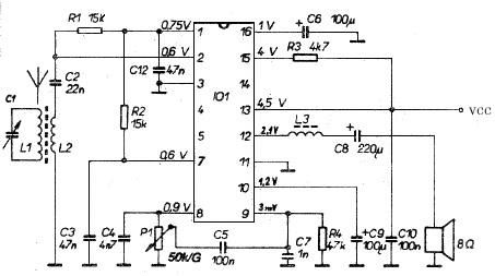
This AM radio receiver circuit utilizes the TDA1083 radio IC, which is suitable for constructing a simple medium frequency (MF) band radio. The schematic operates within a frequency range of 300 kHz to 3 MHz. The circuit is straightforward...
The touch sensor switch circuit diagram features a step-down rectifier circuit, a 555 timer, and flip-flops. When a hand touches the metal sheet A, the sensor signal activates the internal comparator of the 555 timer, setting the output to...