
True Subwoofer Circuit

The true subwoofer circuit operates by utilizing a bass-reflex enclosure, which enhances low-frequency response through the strategic placement of a port or vent. This design allows for the generation of deeper bass tones by utilizing the rear sound wave produced by the woofer. The circuit typically includes an audio amplifier that provides the necessary power to drive the larger woofers effectively, ensuring optimal performance.
Key components of this circuit include a power amplifier, a crossover network, and the woofer itself. The power amplifier is responsible for boosting the audio signal to a level that can drive the woofer, while the crossover network filters out higher frequencies, allowing only the low frequencies to pass through to the subwoofer.
In terms of specifications, the circuit should be designed to handle the power requirements of the 15- to 18-inch woofers, which often demand higher wattage to perform effectively. Additionally, the enclosure's dimensions must be calculated to match the woofer's specifications, ensuring that the resonant frequency aligns with the desired output.
The use of high-quality capacitors and inductors in the crossover network is crucial for maintaining signal integrity and preventing distortion at high volumes. The overall design should prioritize efficient heat dissipation to prevent overheating during prolonged use, especially in high-power applications.
This circuit is ideal for home theater systems, professional audio setups, and any application where deep bass reproduction is critical. Proper implementation of this design will result in a powerful and accurate low-frequency response, enhancing the overall audio experience.This is true subwoofer circuit. This circuit is used for 15- to 18-inch woofers and will not work with 8- or 6- inch subwoofers. It has bass-reflex, a.. 🔗 External reference
Related Circuits
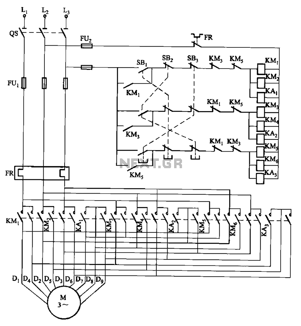
The circuit depicted in Figure 3-115 utilizes contactors and double buttons, allowing for speed conversion without the need to press the stop button. The buttons SBi, SBz, and SB3 correspond to high, medium, and low-speed operation, respectively. This circuit design...
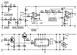
This component is useful for ensuring that the subwoofer is in phase with the speakers of the existing car radio. It utilizes dual-linear motion potentiometers, capacitors, and electrolytic components. The circuit described involves a phase alignment system designed to optimize...
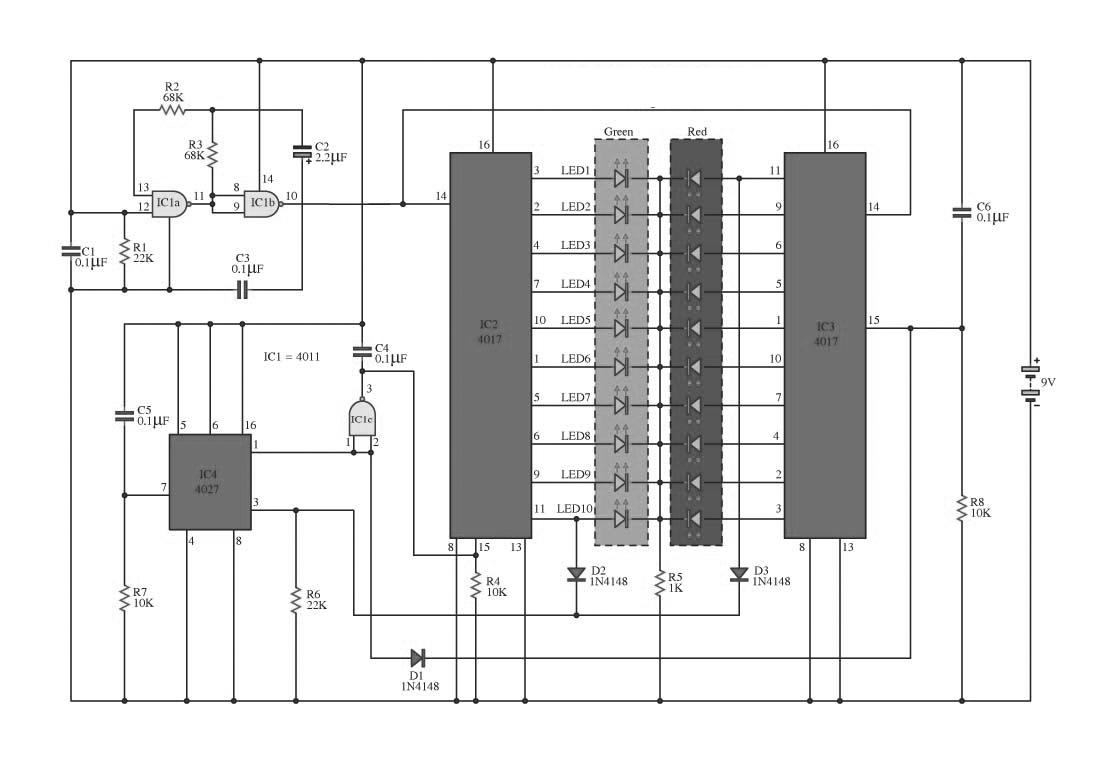
This circuit operates on alternating two colors using a 2-color LED with a built-in 3-pin configuration. It alternates the glow of each LED until the base, switching between two colors. The circuit comprises a NAND gate IC, two 10-counter...
Short circuits in the tracks, points, or wiring are almost inevitable when building or operating a model railway. Although transformers for model systems must be protected against short circuits by built-in bimetallic switches, the response time of such switches...
An electrical circuit that ensures when two or more generators are connected in parallel to a power system, they share the load equally. In this arrangement, if the voltage of one generator is slightly higher than that of the...
The layout of the PC board led to the decision to insert a stereo 3mm canceling type jack (5 pin) at the volume control chip inputs, which was mounted on the front panel. A suitable jack was not available...