
Carrier-Current Baby-Alert Receiver Circuit

The baby-alert receiver circuit is designed to monitor and respond to specific frequency signals, providing an effective alert system for caregivers. The core of the circuit involves three transistors, each serving a distinct purpose to achieve optimal performance.
Transistor Q2 is configured as a high-gain linear amplifier, which amplifies the incoming signal to a sufficient level for further processing. This amplification is critical, as it ensures that even weak signals can be detected and processed effectively. The high-gain configuration allows for minimal distortion, preserving the integrity of the signal.
Transistor Q3 operates in dual capacity as both an amplifier and a detector. In its amplifier role, it further boosts the signal received from Q2, ensuring that it is strong enough for detection. As a detector, Q3 identifies the presence of the specific 125-kHz signal emitted by the alarm transmitter. This dual functionality is essential for the circuit's ability to discern the intended alarm signal from potential noise present in the environment.
Transistor Q4 acts as a switch, controlling the activation of the alarm (BZ1). When Q3 detects the 125-kHz signal, it triggers Q4, which completes the circuit to the alarm. This switching mechanism allows for immediate response to the detected signal, ensuring that the alarm is sounded promptly to alert caregivers.
The additional components in the circuit may include resistors, capacitors, and diodes, which work together to stabilize the circuit, filter out noise, and protect the transistors from voltage spikes. The inclusion of these components is vital for the reliability and longevity of the baby-alert receiver.
The system operates by receiving the 125-kHz signal through the existing 120-V power lines, which serves as a convenient method for signal transmission without requiring additional wiring. This feature enhances the practicality of the baby-alert receiver, making it suitable for various applications in monitoring and alert systems. Overall, the design emphasizes efficiency, reliability, and responsiveness, making it an effective solution for alerting caregivers to the presence of an alarm condition. The baby-alert receiver is comprised of three transistors: Q2, which is configured as a high-gain linear amplifier; Q3, which serves as both an amplifier and detector; and Q4. which is essentially used as a switch; and a few additional components. It sounds an alarm BZ1 on receipt of a 125-kHz signal from an alarm transmitter via the 120-V power lines.
Related Circuits

TV video signal processor circuit. The ECG1064 chip includes a primary video amplifier, two sync pulse amplifiers, a look-out protector, a noise detector, two noise gates, an automatic gain control (AGC) detector, an intermediate frequency (IF) AGC amplifier, a...

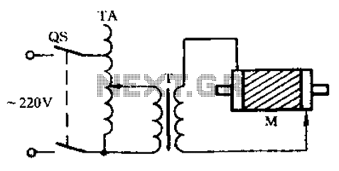
The circuit depicted in Figure 3-84 allows two electric motors to be started independently. The motors can only be activated after pressing the main stop button (SBz) to release contact KMi. Following this, the auxiliary stop button (SB4) can...
A 12-volt power supply is used to operate a sequencer board that controls external relays for coaxial relays, a preamplifier, and an amplifier. The sequencer board features DIL relays designed to drive these external relays. Although there are more...
The file being accessed no longer exists. It may have been renamed or removed from the archive. Navigation links are available on the left to browse the desired area of the archive. The connection is to cdn.preterhuman.net, which mirrors...
Check the three-phase motor with broken bars as shown in the inspection circuit for the three-phase motor with broken bars. The inspection circuit for a three-phase motor with broken bars is designed to diagnose and evaluate the condition of the...
This project is used as an electronic private exchange. It has two telephones, which have the intercom facility, and they can be connected to the telephone line. All the functions are controlled by the 8-bit microcontroller AT89C2051 which has...