
Check the circuit diagram of a three-phase motor with broken bars

The inspection circuit for a three-phase motor with broken bars is designed to diagnose and evaluate the condition of the motor's rotor. Broken bars in an induction motor can lead to significant performance issues, including reduced efficiency, increased heat generation, and potential motor failure. The schematic typically includes key components such as current transformers, voltage sensors, and a microcontroller to analyze the data collected.
The circuit begins with the three-phase supply connected to the motor. Each phase line is monitored by current transformers that provide real-time current measurements. These measurements are essential for identifying imbalances that may indicate broken rotor bars. The output from the current transformers is fed into an analog-to-digital converter (ADC) within the microcontroller.
The microcontroller processes the current data and compares it to predefined thresholds. If an anomaly is detected, such as significant current differences between phases, it triggers an alert signal. This alert can be visualized on an LCD display or sent to a remote monitoring system for further analysis.
In addition to current monitoring, voltage sensors are integrated into the circuit to assess the supply voltage levels. Maintaining proper voltage levels is crucial for the motor's operation, and deviations can further exacerbate issues related to broken bars.
The inspection circuit may also include protective elements such as fuses or circuit breakers to prevent damage from overcurrent situations. Overall, this inspection circuit serves as a vital tool for maintenance personnel to ensure the longevity and reliability of three-phase motors, enabling timely interventions before catastrophic failures occur. Check the three-phase motor with broken bars As shown in the three-phase motor with broken bars of inspection circuit:
Related Circuits
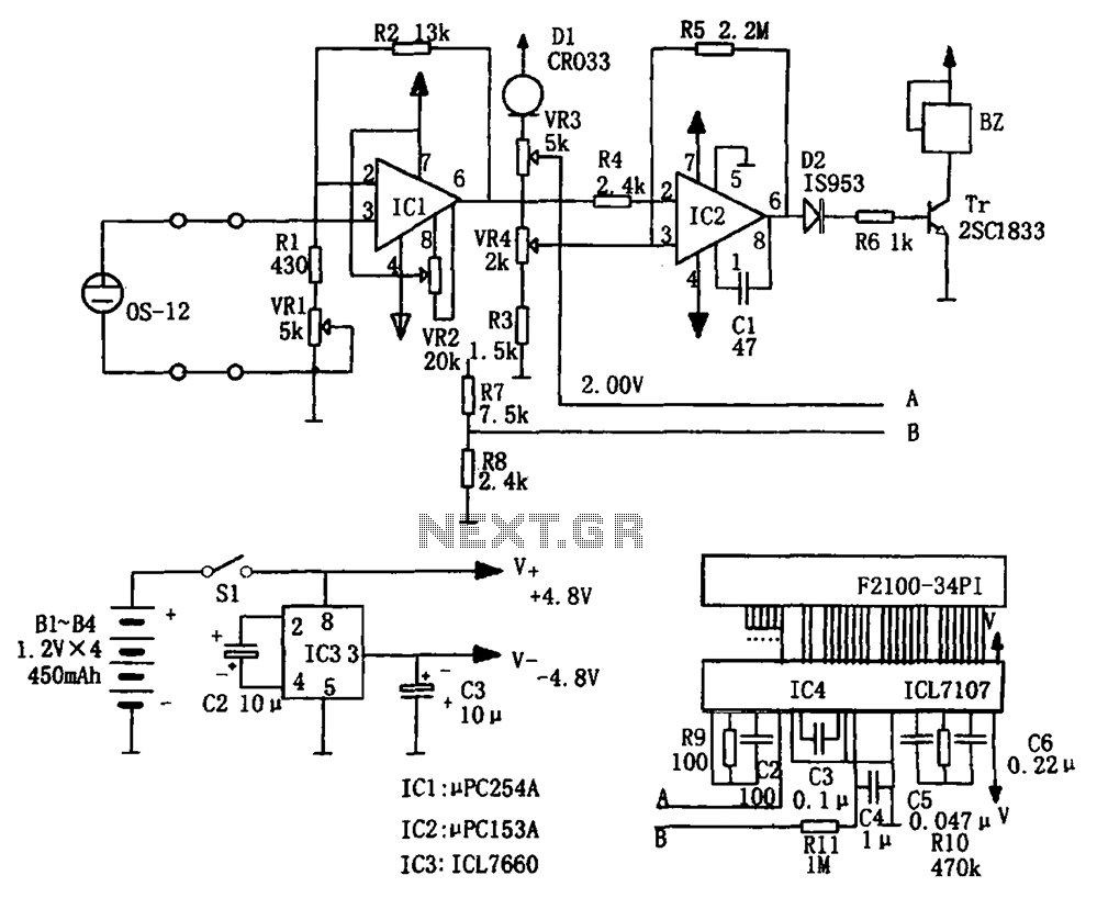
The portable hypoxia monitoring circuit comprises the oxygen sensor OS-12, a DC amplifier IC1, an A/D converter IC4, and a liquid crystal display F2100-34PI. Additionally, it includes a voltage comparator IC2 and a positive and negative power converter IC,...
The circuit consists of two synchronized multivibrators formed by a pair of 555 timer circuits. It is capable of generating two synchronized pulse signals, with the spacing and frequency adjustable by modifying the time constant. The circuit offers flexibility...

This document outlines the design process of a control circuit for a stepper motor. Given the characteristics of the stepper motor, the control circuit was developed as a state machine that transitions through four output states depending on two...
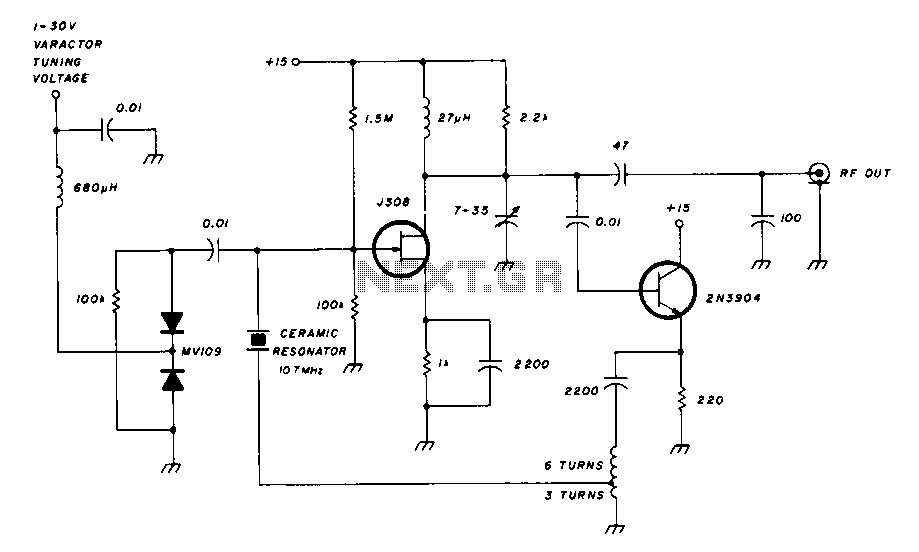
A field effect transistor amplifier features a fixed bias input source with feedback, resulting in very high input impedance and low capacitance. It drives a field effect transistor or emitter follower, despite having a very low output impedance, utilizing...
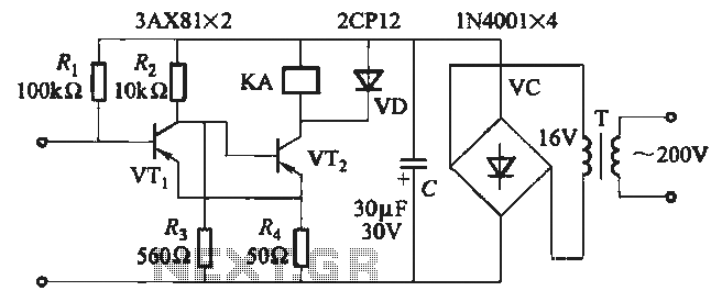
When the input is disconnected, the transistor VTi conducts, while VTz is in cutoff, causing relay KA to release. When the input is shorted, VTi is cut off, VTz conducts, and relay KA is activated. In this circuit configuration, the...
Connect a 12V fan to this circuit that consumes 70mA (0.07A), ensuring the circuit can supply at least that amount of current. There appears to be a misunderstanding regarding the analysis. The voltage drop across the resistor equals the...