
Carrier current receiver

The 60 kHz transformer is designed for efficient energy transfer at high frequencies, making it suitable for applications in power electronics, signal processing, and RF circuits. The choice of an ungapped pot core allows for improved magnetic coupling and reduced losses, which is critical in high-frequency operations. The use of type "F" magnetic material enhances the core's performance by providing low core losses and high saturation flux density, ensuring reliable operation within the specified frequency range.
The winding configuration, with SOV2 turns for the secondary and a calculated number of turns for the primary, is essential for achieving the desired voltage transformation. The turns ratio of approximately 15:1 indicates that the primary winding has 15 times more turns than the secondary winding, which allows for stepping down the voltage efficiently. This transformer can be used in various applications, including power supplies, inverters, and signal isolation, where voltage transformation and impedance matching are required.
In designing the circuit around this transformer, attention must be given to the selection of components that can handle the operating frequency and the corresponding power levels. Proper insulation and thermal management should also be considered to ensure optimal performance and longevity of the transformer in its intended application.60 kHz transformer consists of a 18 x 11mm ungapped pot core (Siemens, Fer-rocube, etc), utilizing magnetics incorporated type "F" material wound with SOV2 turns of No5 wire for the secondary and turns for the primary This gives a turns ratio of approximately 15 to 1.
Related Circuits
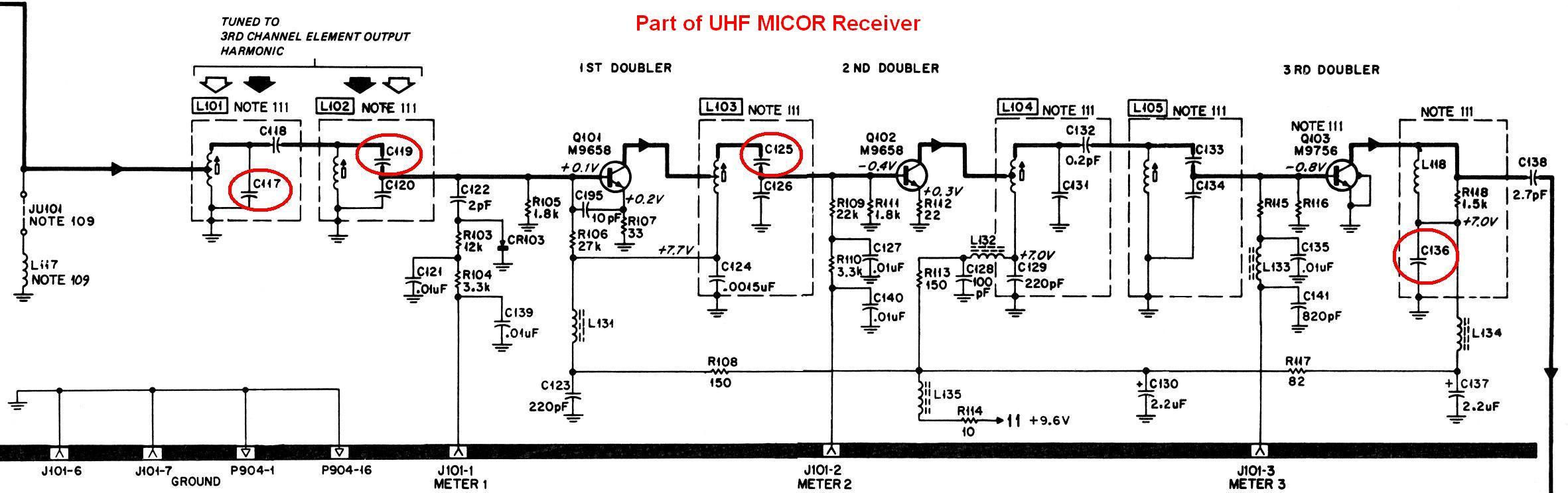
This document provides a detailed explanation of a procedure to modify a UHF MICOR "M" range (450-470 MHz) receiver board for optimal operation within the 435-450 MHz range. This enhancement builds upon Kevin's text-only article. These receivers are typically...
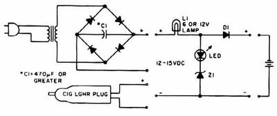
NiCd charger with current and voltage limiting power supply. This is a car NiCd battery charger circuit that can charge any Ni-Cd battery between 4.8 and 4.4 volts from a classic 12 volts car battery. The charging current can...
Most telephone equipment today utilizes a DTMF receiver integrated circuit (IC). A widely used DTMF receiver IC is the Motorola MT8870, which consists of 18 pins and is employed in telephones and various other applications. When projects utilizing this...
The impedance of these current generators is essentially infinite for small currents, and they maintain accuracy as long as VIN is significantly greater than VOS and IO is much higher than I bias. The source employs a FET to...
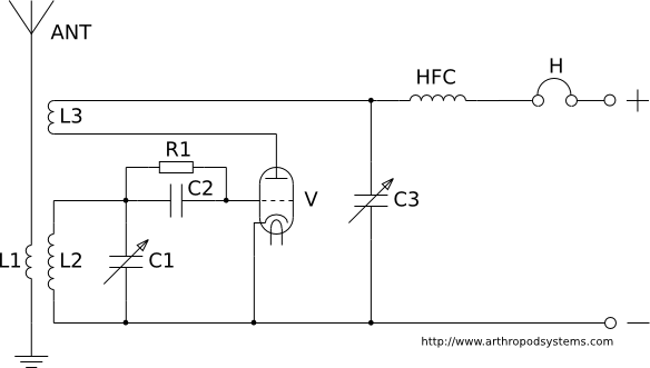
This page discusses various regenerative receiver circuits that were utilized primarily between the 1920s and 1940s. The connections are illustrated using electron tubes (vacuum tubes or valves), although FET transistors can be substituted with minimal adjustments. For radio enthusiasts,...
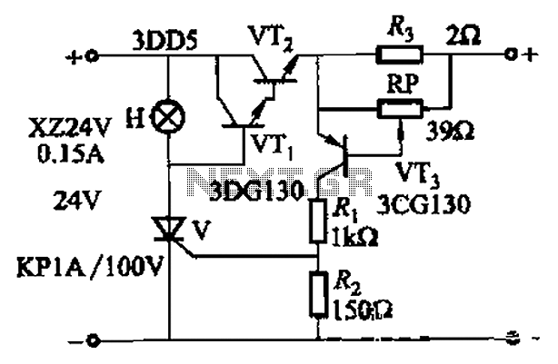
By adjusting Ro or RP, the current setpoint can be modified. The circuit illustrated in Figure 14-98 features overcurrent protection using a thyristor and transistors VTi and VT2, which immediately cut off the power when an overcurrent condition is...