
nicd charger with current and voltage limiting

The described NiCd charger circuit is designed to efficiently charge nickel-cadmium batteries with a specific voltage range of 4.4 to 4.8 volts, utilizing a standard 12-volt automotive battery as a power source. The circuit integrates a current and voltage limiting mechanism to ensure safe and effective charging, thereby preventing damage to the battery due to overcharging.
In this configuration, the charging current is adjustable between 50 mA and 120 mA through a selector switch (S). This adjustability allows users to tailor the charging rate according to the specific requirements of different NiCd batteries and applications. For instance, a lower charging current may be preferable for smaller batteries or to extend battery life, while a higher current may be used for quicker charging of larger capacities.
The circuit typically includes essential components such as a transformer to step down the voltage, a rectifier to convert AC to DC, and a voltage regulator to maintain a stable output voltage. Additionally, protection diodes may be implemented to prevent reverse current flow, ensuring the longevity of both the charger and the batteries being charged.
This charger is particularly advantageous for users in remote areas or situations where access to standard electrical outlets is limited. Its application spans various fields, including model making, video production, and any other scenarios where portable power solutions are necessary. The design emphasizes user-friendliness and adaptability, making it a valuable tool for individuals reliant on NiCd batteries.NiCd Charger with Current and Voltage Limiting power supply. Go to that page to read the explanation about above power supply related circuit diagram. This is a car nicd battery charger circuitthat can chargeanyNi-Cdbatterybetween 4. 8 and4. 4 voltsfromaclassic12Voltscar battery. Thecharging currentis constan titcan beselected from the values of 50 to120mAbythe selectorS. This feature is veryuseful formodel makingenthusiasts, forvideooperators, to those who usesmall appliancestransmissionandreceptionto all thosethat useNi-Cdbatteriesand needto rechargeorvoltagenetworkis not available. . 🔗 External reference
Related Circuits
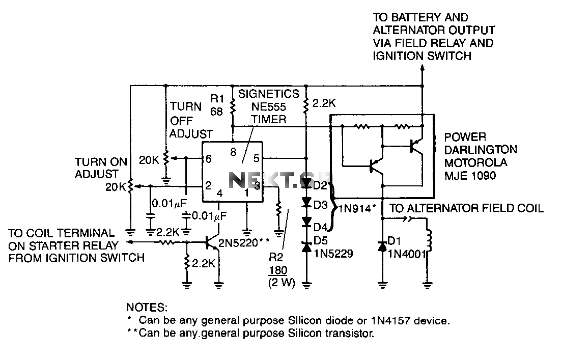
A monolithic 555-type timer serves as the core component of this straightforward automobile voltage regulator. When the timer is inactive, resulting in a low output at pin 3, the power Darlington transistor pair remains off. If the battery voltage...
In appliances that require alternating current, NiCad (NiCd) rechargeable batteries still demonstrate significant performance advantages compared to NiMH and lithium batteries. The charger circuit is critical in handling incorrect polarity of the battery placement. The core of this battery...
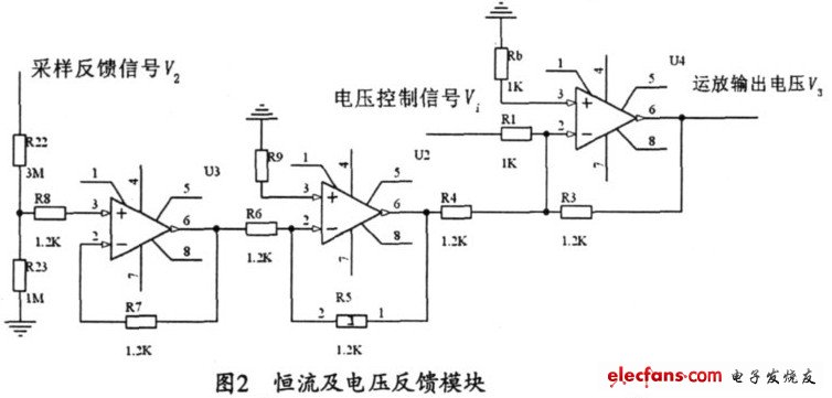
The output current range of the parameter current regulator is limited, and its precision is not high. Connecting the feedback adjustment type output current of the current-stabilized power source in series results in lower efficiency. The steady current source...

This is a simple and low-cost NiCd and NiMH battery charger. The schematic diagram indicates that the charging current (I) should be set to 1/10 of the battery's rated capacity. For instance, if the battery has a rated capacity...
Here we use the PIC16711. Rechargeable battery capacity is rated in mAH (milliampere-hours). The total capacity of a battery is defined as "C", that is it can supply C mA for 1 hour, or 2C for 30 minutes etc....
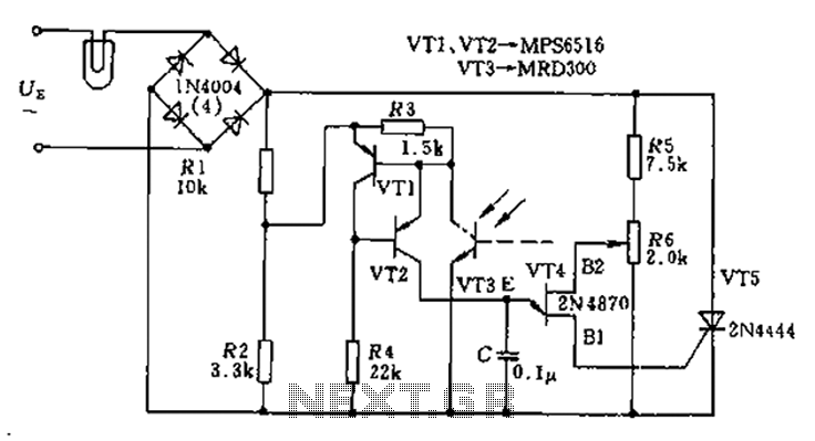
The circuit utilizes a thyristor-based AC automatic voltage regulator to stabilize the brightness of lamp L. A diagonal line connects the thyristor to the T5 bridge. The trigger pulse for the thyristor is generated by a single-junction transistor, VT4....