
Case Modding
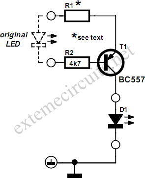
The proposed circuit modification enhances the visual output of LED indicators in PC enclosures while ensuring compatibility with typical motherboard configurations. The primary components include a transistor, which acts as a switch, and two resistors that set the appropriate current levels for the high-brightness LEDs. The transistor is connected to the motherboard LED driver output, allowing it to control the higher current needed for bright LED operation without overloading the motherboard's LED driver.
For the implementation, R1 is calculated based on the desired current for the LED type being used. For instance, if a high-brightness red LED is chosen, a resistor value of 150 ohms would be appropriate to limit the current to 20 mA. Conversely, for a high-brightness blue LED, a resistor value of 75 ohms would suffice to maintain a 10 mA current. The second resistor, often referred to as R2, can be used to provide additional stability in the circuit, minimizing fluctuations in current that could affect LED brightness or longevity.
The circuit's design should ensure that all connections are secure and that the perforated board is appropriately mounted within the PC enclosure to avoid short circuits. Additionally, the choice of grounding point is crucial; using a reliable ground connection will ensure that the LED operates effectively and that the circuit remains stable.
In summary, this modification not only increases the brightness of the LED indicators in PC enclosures but also preserves the integrity of the motherboard's LED driver. By carefully selecting resistor values and ensuring proper grounding, users can achieve a visually appealing enhancement to their PC's aesthetic without compromising functionality.The aesthetics of case modding` (modifying a PC`s enclosure) offer plenty of scope for debate and plenty of scope for original circuits. Low current LED indicators are usuallytted in PC enclosures. Although this certainly saves energy, the LEDs do not light particularly brightly. It is not completely straightforward to replace the low-current types with high-brightness types since the latter draw a current of 20 mA rather than 2 mA. This can - whatever people might tell you to the contrary - in some instances lead to excessive load on the LED drivers on the motherboard. The problem can be solved using a small external driver stage: two resistors and a transistor mounted on a small piece of perforated board, connected in place of the original LED.
The new high-brightness LED is then connected between the output of the current source and a spare motherboard ground connection (for example on the infrared port) or to a grounded screw in the enclosure. R1 is responsible for the constant current. High-brightness red LEDs are driven at 20 mA (R1 = 150 ), whereas high-brightness blue LEDs require 10 mA (R1 = 75 ).
In view of the large number of different PC motherboards available, it is not certain that this driver can be used in every PC. It is easy to check whether the circuit will work: use a DC voltmeter to measure the voltage between the positive connection on the LED (generally a red wire or a pin marked with an arrow on the LED connector) and ground (not the other pin of the connector).
If this reads +5 V independent of whether the LED is on or not, then the driver can be used. 🔗 External reference
Related Circuits
Some time ago, an electronic hobbyist sought to create a logic analyzer. As a DIY enthusiast, a simple yet effective logic analyzer was constructed. Utilizing an old Pentium III laptop equipped with a single LPT port, a search for...
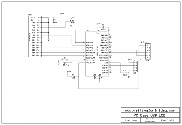
The first version of an Open Source Framework for USB Generic HID devices based on the PIC18F and Windows includes an example of how to utilize the library with a USB interface for an LCD. With the completion of...

Recently, the Overunity and Energetics online forums, which serve as significant platforms for members of the Open Source and Free Energy communities, have been discussing a remarkable phenomenon known as the Rosemary Ainslie Circuit. This circuit is named after...

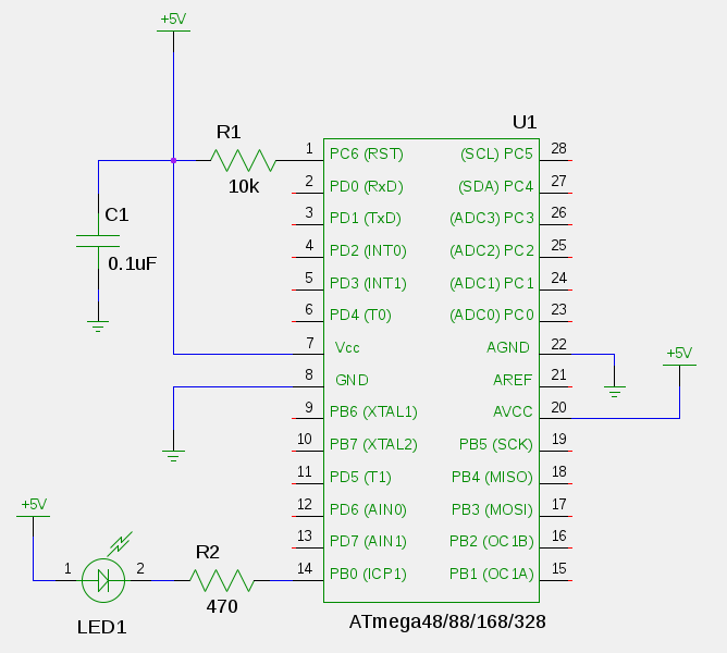
The schematic diagram and electronic assembly are relatively simple, as most of the functionality is managed by the microcontroller code. The schematic diagram serves as a visual representation of the electronic circuit, outlining the connections between various components such as...
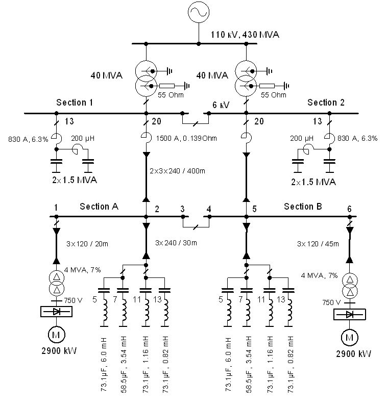
The vertical line indicates the instance of the 5th harmonic filter connection. The diagram illustrates the power system with the designed group of single-tuned filters for a system with a DC drive supplied by a 6-pulse controlled rectifier: PN...

Light Sensitive Staircase Switch with Triac. The operation of the third circuit is similar, except that it incorporates photo sensitivity. The circuit is illustrated in the schematic. When there is insufficient light... A light-sensitive staircase switch utilizing a TRIAC is...