Light Sensitive Staircase Switch with Triac

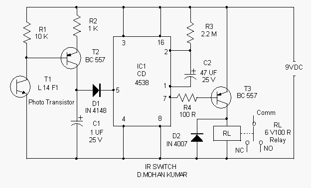
Light Sensitive Staircase Switch with Triac. The operation of the third circuit is similar, except that it incorporates photo sensitivity. The circuit is illustrated in the schematic. When there is insufficient light...
A light-sensitive staircase switch utilizing a TRIAC is designed to control lighting based on ambient light levels. This circuit operates by detecting the presence of light through a photoresistor (LDR), which serves as the primary sensor for light intensity.
In the schematic, the photoresistor is connected in a voltage divider configuration with a fixed resistor. This arrangement allows the circuit to produce a variable voltage that corresponds to the light level. When the light intensity falls below a certain threshold, the resistance of the LDR increases, causing the voltage at the junction of the LDR and the resistor to rise.
This increased voltage is fed into the gate of the TRIAC, which controls the power to the lighting load. The TRIAC remains in the conductive state once triggered, allowing current to flow through the load until the current drops below a certain level (zero crossing). The design ensures that the lights can be turned on or off based on the ambient light conditions, providing energy efficiency and convenience.
The circuit may also include additional components such as a capacitor for snubber protection to prevent voltage spikes, and a diode for reverse polarity protection. The use of a TRIAC allows for smooth dimming capabilities, enabling the user to adjust the brightness of the lights based on their preferences and the surrounding light conditions.
Overall, this light-sensitive staircase switch circuit offers a practical solution for automatic lighting control, enhancing both safety and energy efficiency in stairwell applications.Light Sensitive Staircase Switch with Triac , Operation of the third circuit is much similar except that it has photo sensitivity. The circuit is shown in Schematic When there is no sufficient l.. 🔗 External reference


