
Cat / Dog Detector

The main advantage of this unit is that it does not require any battery on the animal, as is the case with most store-bought devices for this purpose. The single-turn coil can be joined with plugs so it can be removed easily. However, if the plug comes apart or has a poor connection, the door won't open. Therefore, it is better to make the coil just barely big enough to slip over the animal's head and solder it to make a solid loop, then tape it to the animal's collar. The larger the diameter of this coil, the greater the sensitivity will be. Additionally, it is important that the cat or dog door and the surroundings do not contain any large pieces of metal. This circuit also functions as a metal detector, and this detector sees the single loop of wire as a solid piece of metal. Furthermore, the coil on the door needs to be mounted in such a way that the coil on the animal can actually get almost inside the coil on the door. A round or rectangular extension outward from the door may be needed to accomplish this. Ideally, the coil on the door will have an inductance of about 150 µH. An inductance calculator can determine this for a round coil.
This circuit operates by using electromagnetic induction to create a signal when the two coils are in proximity. The tuned coil on the door is designed to resonate at a specific frequency, which is achieved by selecting the appropriate inductance and capacitance values. When the animal approaches the door, the single wire loop on its collar, which acts as a secondary coil, couples with the primary coil on the door. This coupling generates a voltage in the primary coil, which can be used to activate an LED indicator and a solenoid mechanism.
The solenoid, which is responsible for unlocking the door, requires careful selection to ensure that it operates effectively with the generated signal. The design should account for the physical characteristics of the door and the solenoid's power requirements. Additionally, the PCB layout should accommodate the tuned circuit components, ensuring minimal interference and optimal performance.
For optimal function, the installation of the coils should be done with precision. The coil on the door should be positioned such that it allows for maximum coupling with the collar loop. This may require adjustments in the mounting position or the use of extensions to facilitate the necessary proximity. The overall effectiveness of the system can be influenced by environmental factors, including the presence of metallic objects nearby, which may interfere with the electromagnetic field.
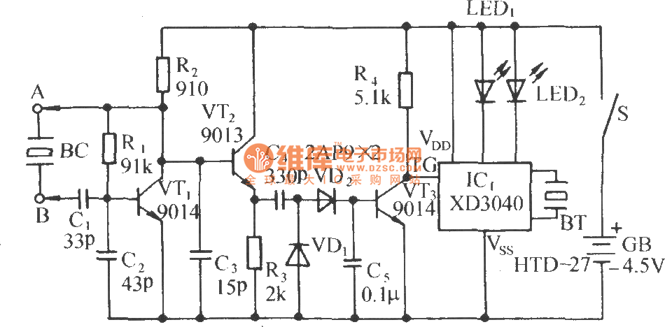
In conclusion, this circuit provides a practical solution for controlling access through a pet door without the need for batteries on the animal. Proper construction and installation are essential for reliable operation, and attention to the physical placement of components will enhance the system's performance.This can be used to control entry on a Cat or Dog Door" NOTE: There may be some changes and improvements coming. However this circuit does work and you can build it as shown. The PCB Shown below is Available from me, or make it yourself. It Measures 2.75" by 1.1". This circuit uses one tuned coil for on the door and just a single wire loop on the animals collar. When the two coils come close together, it produces a signal that can cause a an LED to light and also trips a solenoid to unlock the door so it can open.
Since all these doors are somewhat different, I leave The Solenoid and Mechanical Parts of this design for you to figure out. The Main Advantage of this unit is it does Not Require any Battery on the animal, as is the case with most store bought devices for this purpose. The Single turn coil can be joined with plugs so it can be removed easly. But if the plug comes apart or has a poor connection, the door won't open. So Better yet, make it Just Barely big enough to slip over the animals head, and Solder it to make a solid loop, than tape it to the animals collar.
And the Larger the diameter of this coil, the Greater the Sensivity will be. Also Important, the Cat or Dog door and the surroundings "Can't contain any large pieces of metal". (This circuit is also a Metal Detector and This detector see's the Single Loop of wire as a solid piece of metal.) Additionally, the coil on the door needs to be mounted in such a way that the coil on the animal can actually get almost inside the coil on the door. Possibly a Round or Rectangular Extension, outward from the door will be needed to accomplish this. Either way, the coil on the door will probably need to be mounted a few inches from the door. Ideally the coil on the door will have an inductance of about 150 uH. My Inductance calculator can determine this for a Round Coil. 🔗 External reference
Related Circuits
The circuit consists of a capacitance three-point oscillator, an isolation level, a voltage doubler rectifier circuit, a stereo sound circuit, and a flash display circuit. It can detect the quality of a crystal; a good crystal will emit a...
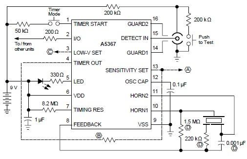
A simple ionization smoke detector with interconnect and timer alarm circuit can be constructed using the A5367 low-current, CMOS circuit, which provides all essential features for an ionization-type smoke detector. This CMOS IC, manufactured by Allegro MicroSystems, includes interconnect...
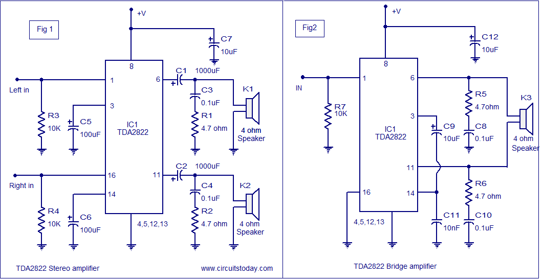
The TDA2822 audio amplifier circuit provides 1.35W output into a 4-ohm speaker when powered by a 6V supply. It supports both bridge and stereo modes and operates within a supply voltage range of 3V to 15V, making it suitable...
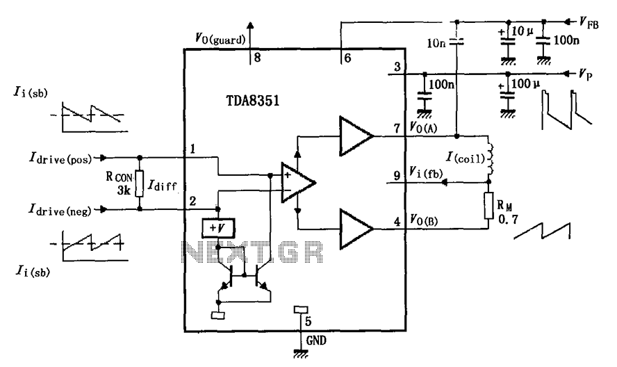
The figure illustrates the actual application circuit for the TDA8351/8356. In this circuit, a 50V voltage feedback (VFB) is connected in series with a 33-ohm resistor. Signals are input at pins 1 and 2, where pin 1 receives a...

If R, the sensor matching resistor, is equal to the "dark" resistance of the cadmium sulfide cell, the amplifier output will range from 0 to 2 as the light level varies from "dark" to "bright." The circuit operates similarly,...
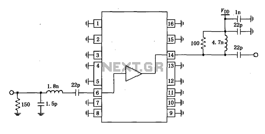
A narrowband linear amplifier circuit configured with the RF2320 operates within a frequency range of 1930 to 1990 MHz. The radio frequency (RF) signal is input from a distance of 6 feet and is amplified by an internal amplifier...