
TDA8351 8356 application circuit

The TDA8351/8356 application circuit is designed for use in television and display systems, where precise control of deflection currents is essential for image stability and quality. The circuit operates by generating opposing sawtooth voltage signals at pins 1 and 2, which are crucial for controlling the deflection coils in cathode-ray tubes (CRTs) or similar display technologies. The resistor Rcon, situated between the input pins, plays a vital role in regulating the current through the deflection coils, ensuring accurate deflection of the electron beam.
The internal differential amplifier processes the input signals, amplifying the difference between them, which is then fed into a push-pull output stage. This configuration allows for efficient driving of the deflection coils, providing a strong and responsive control signal. The output at pin 7 produces a positive sawtooth waveform, while pin 4 delivers the corresponding negative sawtooth waveform, creating the necessary alternating current for deflection.
The inclusion of the feedback resistor RM is critical for improving the linearity of the output waveforms. By connecting RM in series with the deflection coil, the circuit can adjust the feedback voltage at pin 9, enhancing the performance of the sawtooth generator. This feedback loop not only stabilizes the output but also broadens the dynamic range, allowing for more precise control over the deflection process.
Overall, the TDA8351/8356 application circuit exemplifies a sophisticated approach to managing voltage signals for display applications, ensuring that the generated waveforms are both linear and dynamic, which is essential for high-quality image rendering. As shown in the figure shows the actual application circuit TDA8351/8356, when the 50V VFB 60V, VFB in series with the input of a 33 resistor. Signals are input 1,2 feet, these are two sawtooth voltage signal opposite in phase, positive sawtooth voltage input pin 1, pin 2 negative sawtooth voltage input. 1,2 feet between a resistor in parallel Rcon to determine the deflection current through the coil. After an internal signal of the differential amplifier and push-pull power amplifier output to the deflection by a 7,4 feet across the coil.
7 feet sawtooth voltage waveform pulse, 4 feet sawtooth voltage waveform is negative. RM resistor in series with the deflection coil, provided by the feedback voltage input pin 9, the linear sawtooth output is improved, and expand the dynamic range of the sawtooth wave.
Related Circuits
The project involves a DC geared motor intended for use in a suitcase carrier. Two motors were purchased from Pololu at a cost of approximately $100. The selection process included discussions among team members, followed by consultation with Dr....
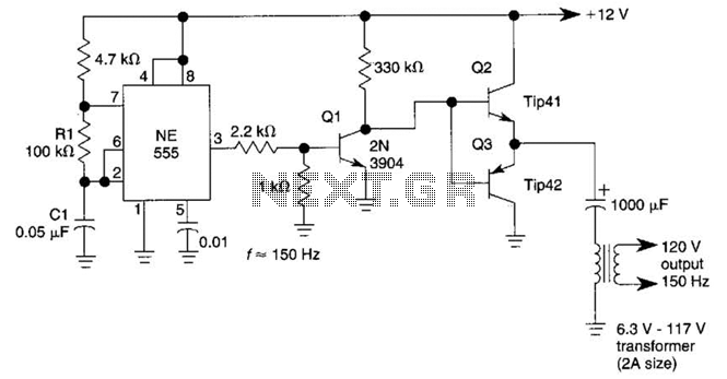
This DC-to-AC inverter utilizes the well-known 555 timer IC. A 555 oscillator circuit drives a buffer amplifier composed of transistors Q1, Q2, and Q3. The circuit operates at a frequency range of 150 to 160 Hz. Transformer T1 can...
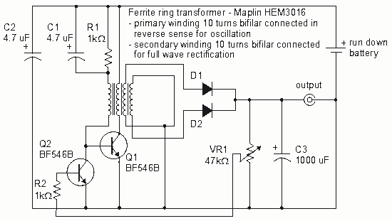
How to create a Joule Thief circuit to power a clock, including circuit details and tips for construction. The Joule Thief circuit is a simple and efficient boost converter that allows the extraction of usable voltage from low-voltage sources, such...
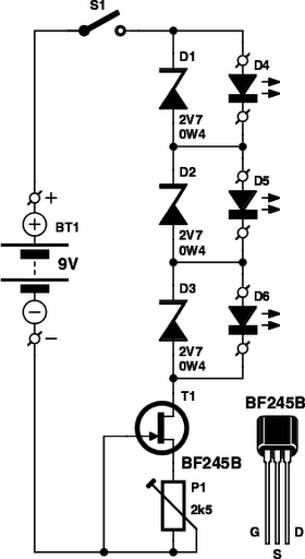
These small electronic lamps are quite practical and have a long lifespan. Approximately 40 years after Nick Holonyak invented the first LED, they have become nearly essential. Any dedicated electronics enthusiast typically keeps a few in their collection. Prior...

The TDA6106Q test circuit, as depicted in the provided figure, operates with a feedback factor of 1/116. The input signal, Vin, is received from the input network consisting of resistors R1, R9 and capacitors C1, C2. The TDA6106Q IC...
This circuit utilizes the AD639 universal trigonometric function generator from Analog Devices to transform a triangle waveform, which serves as the fundamental waveform of the VCO, into a low-distortion sine wave. By operating the AD639 in its frequency tripler...