cb fm 27mhz receiver diagram
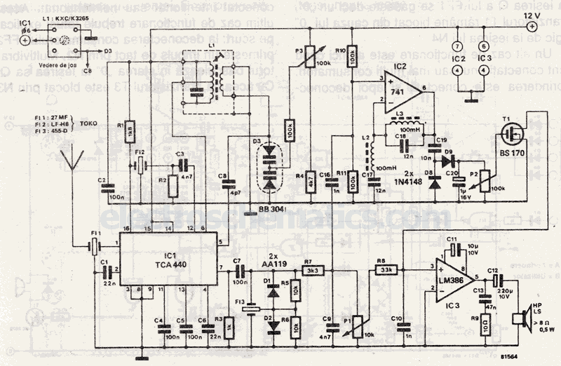
The selection is made with ceramic filters. This 27 MHz receiver operates with an intermediate frequency of 455 kHz.
The circuit employs ceramic filters for signal selection, which are known for their high selectivity and low insertion loss. Ceramic filters are particularly advantageous in RF applications due to their compact size and stable performance over temperature variations. In this 27 MHz receiver, the primary function of the ceramic filters is to allow the desired 27 MHz signal to pass while attenuating unwanted frequencies, thereby enhancing the overall signal quality.
The receiver utilizes an intermediate frequency (IF) of 455 kHz, which is a common choice in superheterodyne receiver designs. The superheterodyne architecture allows for better selectivity and sensitivity compared to direct conversion receivers. The incoming 27 MHz RF signal is mixed with a local oscillator signal, typically generated by a crystal oscillator, to produce the 455 kHz IF signal. This mixing process is facilitated by a mixer circuit, which is crucial for down-converting the RF signal to a more manageable frequency for further processing.
Following the mixing stage, the 455 kHz IF signal is filtered through additional IF filters, which may also be ceramic filters, to further suppress unwanted signals and noise. The filtered IF signal is then amplified using an IF amplifier, which enhances the signal strength before demodulation. Demodulation can be achieved using various techniques, such as envelope detection or synchronous detection, depending on the modulation format of the incoming signal.
The final output of the receiver can be sent to an audio amplifier or a microcontroller for further processing or decoding, depending on the application requirements. Overall, the use of ceramic filters and the superheterodyne architecture in this 27 MHz receiver design ensures high performance and reliability in receiving RF signals.The selection is made with ceramic filters. This 27 MHz receiver works with an intermediary frequency of 455 kHz. 🔗 External reference
