
1990 Toyota Corolla Brake Light Wiring Diagram

No description available.
Related Circuits
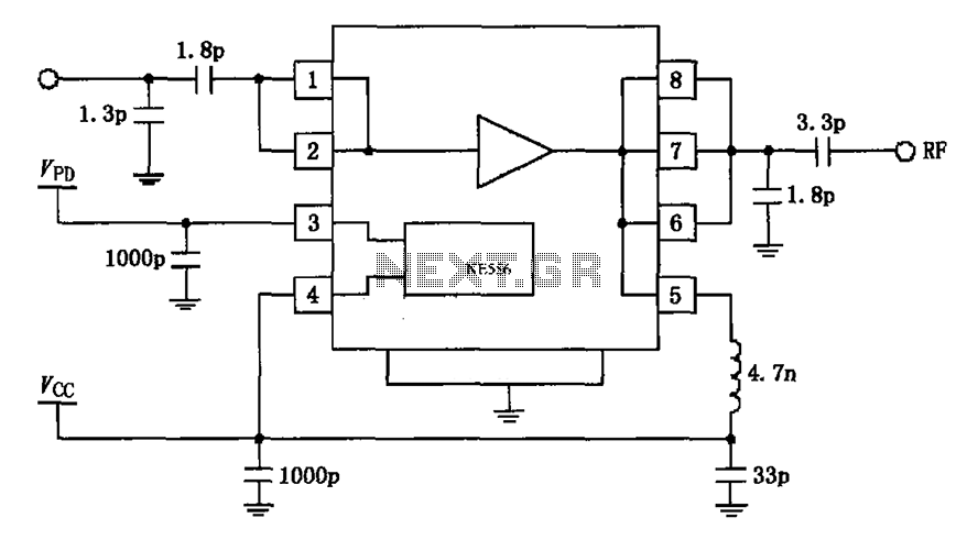
The circuit depicted in the figure is based on the RF2126, a 2450 MHz end-stage linear power amplifier. The radio frequency (RF) signal enters through input pin 1 and is subsequently amplified by the amplifier stages (pins 5, 6,...
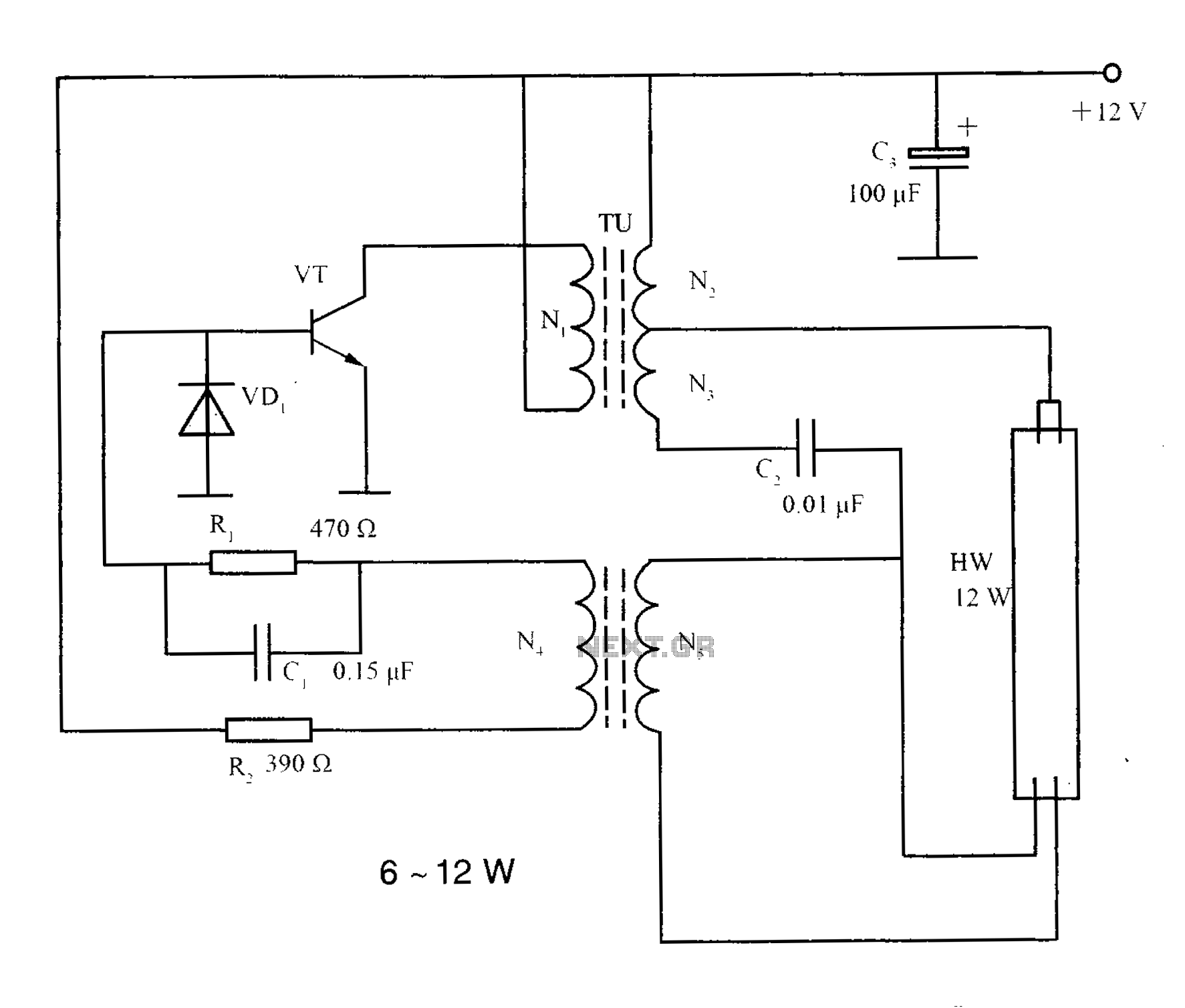
The lighting inverter circuit is designed for 6 to 12W fluorescent lamps. It operates by first bucking the mains voltage, followed by rectification and filtering to charge a battery. When the inverter is activated, it generates a high-frequency alternating...
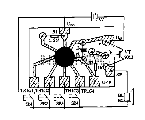
This is an Auto OFF Light circuit. After the switch is pressed, the bulb remains illuminated for a few seconds. To increase the ON time, a 10k resistor should be used. The Auto OFF Light circuit is designed to provide...
Circuit for Grundig 5441 TV. If there are any issues related to this circuit, please provide additional information about the problem for further assistance. By accessing the Fixya site, users acknowledge that they have read and agreed to its...
Constantly changing light and sound analog controller circuit 07 The circuit described is an analog controller designed to modulate light and sound in a dynamic manner. This circuit utilizes various electronic components to create an interactive experience where both light...
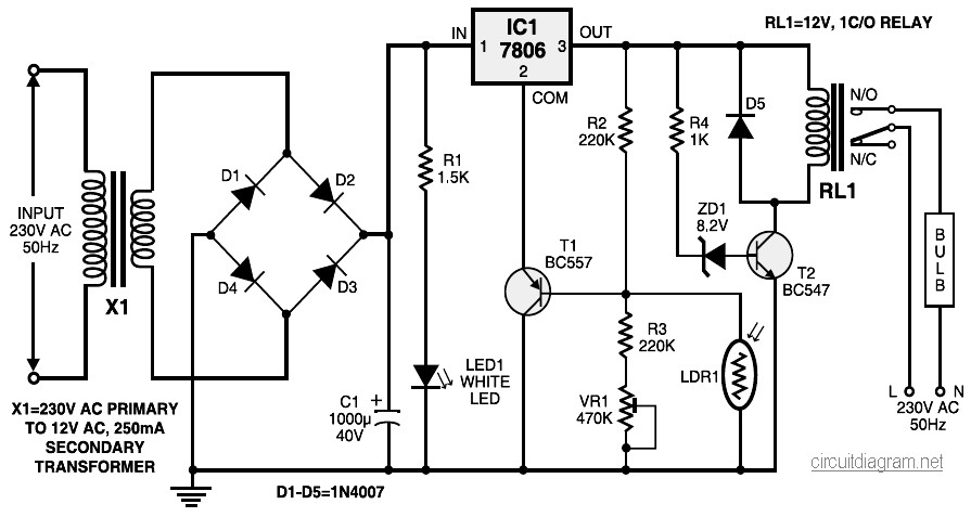
During nighttime, when no light falls on LDR1, it offers a high resistance at the base junction of transistor T1. Consequently, the bias is significantly reduced, and T1 does not conduct. This effectively removes the common terminal of IC1...