
Electronic fishing shrimp machine circuit diagram 2

The electronic fishing shrimp machine operates through a carefully designed circuit that integrates multiple components to achieve its functionality. The astable oscillator serves as the timing mechanism, generating a continuous square wave output. This is accomplished by configuring the time-base integrated circuit along with the associated resistors and capacitors, which determine the frequency of oscillation. The inclusion of diodes in this section ensures that the circuit operates efficiently by managing the direction of the current flow.
The inverter circuit plays a crucial role in converting the low voltage signals from the oscillator into high voltage signals suitable for driving the high-voltage output circuit. Transistors V1 and V2 act as switches, modulating the current through transformers T1 and T2, which step up the voltage levels. The use of a potentiometer (RP1) in this section allows for fine-tuning of the inverter's output frequency, enabling the user to adjust the performance of the machine based on specific fishing conditions.
The high-voltage output circuit is responsible for generating the electrical signals that attract shrimp. Transformer T2 increases the voltage to a level that can energize the relay (K), which in turn controls the flow of current to the output components. Diodes VD1, VD2, and VD6 protect the circuit from back EMF generated by the inductive loads, ensuring longevity and reliability. The capacitors (C1 and C2) filter the output signal, smoothing out any fluctuations and providing a stable output. The neon light (HL) serves as an indicator, illuminating when the circuit is active, while electrodes A and B are positioned to create the electric field necessary for attracting shrimp.
In summary, the electronic fishing shrimp machine circuit is a complex assembly of components working in unison to create an effective device for attracting marine life. Each section of the circuit is designed to perform specific functions that contribute to the overall operation of the machine, allowing for adjustments to be made to optimize performance in various aquatic environments.The ectronic fishing shrimp machine circuit is composed of the astable oscillator, inverter circuit, high voltage output circuit, and the circuit is shown as the figure 20. Astable oscillator circuit is composed of the time-base integrated circuit IC, resistors R3, R4, potentiometer RP2, diodes VD4, VD5 and capacitors C4, C5.
Inverter circuit is c omposed of the transistors V1, V2, transformers T1, T2, resistor R1, potentiometer RP1, diode VD3 and capacitor C3. High-voltage output circuit consists of the transformer T2, relay K, diodes VD1, VD2, VD6, resistor R2, capacitors C1, C2, neon light HL and the electrodes A, B.
Adjusting the resistance of RP1 can change the oscillation frequency of the inverter circuit. 🔗 External reference
Related Circuits
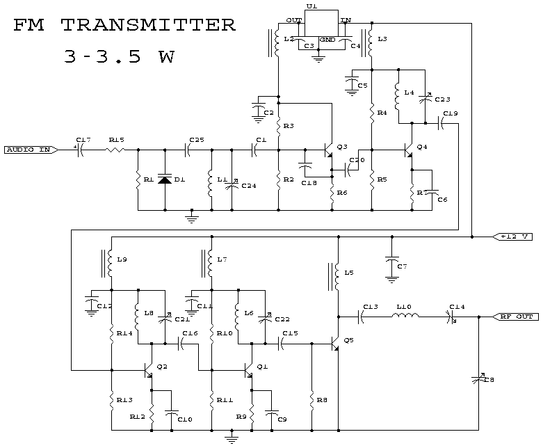
This schematic represents an FM transmitter capable of delivering an output power between 3 to 3.5 W, operating within the frequency range of 90 to 110 MHz. While the stability of the circuit is acceptable, the integration of a...
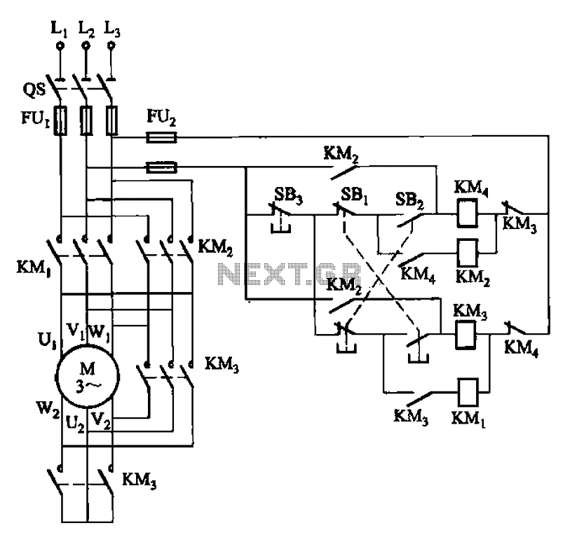
33 kW and above windlass with Y-conversion power-saving circuit The circuit design for a windlass rated at 33 kW and above incorporates a Y-conversion power-saving mechanism. This design is crucial for optimizing the efficiency of the windlass, which is commonly...
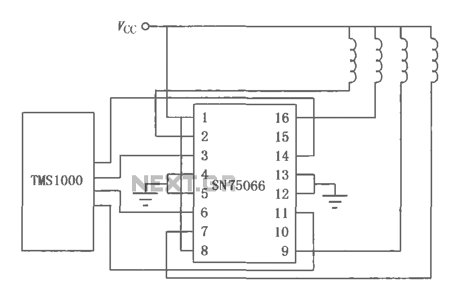
The SN75064 to SN75067 series consists of monolithic, high-voltage, high-current Darlington switch output terminations. These devices include clamp diodes, making them suitable for inductive loads. Each package contains four Darlington pairs that can be connected in parallel to achieve...

How many speakers can be attached to this amplifier, and what are the impedance and wattage values of these speakers? Please respond to my email. Sir, you made this amplifier, and it works properly for a lifetime. Which transformer...
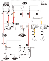
This circuit below shows an electrical circuit applicable for the Audi A4 Quattro 2004 model year. Component: Transmission, Anti-lock Brakes Circuit. The electrical circuit for the Audi A4 Quattro 2004 model year encompasses critical components such as the transmission system...
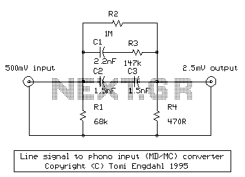
Many amplifiers have phono inputs for connecting record players to the amplifier. Phono input is designed to take a up to few millivolt signal from phono pickup and amplify it. The amplifier stage does also some equalization based on...