
Cb modulation monitor

This circuit is designed for measuring the percentage of modulation in a transmission line by interfacing with a transceiver. The use of a coaxial T connector allows for seamless integration into the transmission line without significant signal loss.
Upon connecting the circuit, the transmitter should be keyed in an unmodulated state, ensuring that the signal being analyzed is a constant carrier wave. Setting switch 31 to the CAL position is essential for calibrating the circuit, allowing it to provide accurate readings. The adjustment of resistor R2 is critical; it must be fine-tuned to achieve a full-scale reading on the meter, which indicates that the circuit is properly calibrated to the specific characteristics of the transceiver and the modulation being measured.
Once calibrated, switch SI should be returned to the MOD position. In this configuration, the circuit will measure the modulation depth of the signal, providing a readout on the meter that reflects the percentage of modulation. The meter is designed to deliver readings with an accuracy of 10%, which is sufficient for many practical applications in radio transmission and communication systems. This level of accuracy ensures that users can monitor modulation levels effectively, facilitating optimal performance and compliance with transmission standards.
This circuit is particularly useful in settings where modulation levels must be monitored and adjusted to meet specific criteria, such as in broadcasting, amateur radio, and communications testing environments. Proper operation and calibration of this circuit contribute to enhanced signal quality and reliability in radio frequency applications.Connect this circuit to a transceiver with a coaxial T connector in the transmission line. Key the transmitter (unmodulated), set 31 to CAL, and adjust R2 for a full scale reading. Return SI to MOD position The meter will read % modulation with 10% accuracy.
Related Circuits
Figure A illustrates the circuit of a direct-trigger timing light. The trigger voltage is obtained from the vehicle's ignition circuit via a direct connection to a spark plug. Figure B depicts a circuit utilizing an inductive pickup. A trigger...
Many electronics hobbyists have encountered the situation where a project is being completed late at night and the mains supply fails. The cause of the failure, whether due to the electricity provider or personal oversight, is not significant. In...
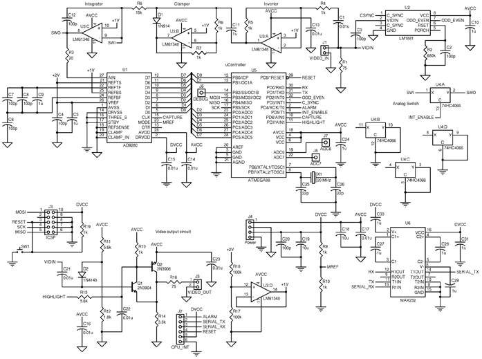
The circuit includes an ATmega88 as the main controller, an AD9280 ADC, an LM6134 high-speed quad op-amp, an LM1881 video sync separator, a 74HC4066 as a simple analog switch, and an RS-232 level converter. The LM1881 video sync separator...

This device is a functionally complete, four-quadrant analog multiplier. The term "four-quadrant" indicates that both operands involved in the multiplication can assume any polarity, either positive or negative, allowing multiplication across all four quadrants. It features high-impedance differential X...
A circuit for monitoring supply voltages of ±5 V and ±12 V can be constructed as shown in the diagram. It is significantly simpler than the typical monitors that utilize comparators and AND gates. The circuit is not designed...
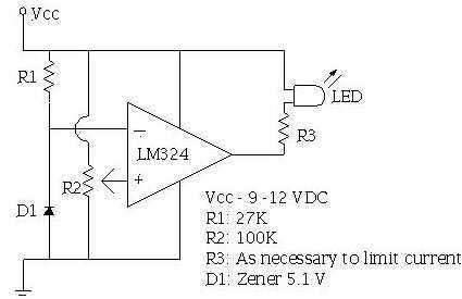
An ECU must have a way to monitor battery voltage. Here is a simple op-amp based circuit which will illuminate the LED when the battery voltage drops to a certain level. The turn-on point is set with R2. You...