
mains voltage monitor

The circuit described functions as an emergency lighting solution, designed to activate in the event of a mains power failure. The core components include a mains voltage monitor, a battery power source, and an alert system comprising LEDs and a buzzer. The voltage monitor continuously checks for the presence of mains voltage. Upon detecting a loss of power, it triggers the activation of five high-intensity LEDs, ensuring sufficient illumination in dark conditions.
The power source for the LEDs is a rechargeable 9 V battery or an array of seven AA cells, providing flexibility in battery choice. The design incorporates a relay (Re1) that plays a crucial role in both charging the battery and controlling the activation of the emergency lights. When mains power is available, the relay closes, allowing current to flow through diode D8 and resistor R10. The resistor is strategically chosen to limit the charging current to a safe level, preventing damage to the battery from overcharging.
Diode D8 also prevents back-feeding of the battery voltage to the relay, ensuring that the relay is deactivated when mains power is lost. This is an essential feature for the reliable operation of the emergency lighting system. The presence of diode D6 provides a visual indication of mains power availability, serving as an additional layer of user feedback.
Once the mains power is interrupted, the relay opens, and the system switches to battery power. Integrated circuit IC1, powered by the battery, activates the JK flip-flops through the resistor R12 and capacitor C4. This activation leads to the conduction of transistors T1 and T2, which subsequently energize the five LEDs (D1-D5) and the buzzer. The buzzer serves as an auditory alert, effectively waking the user if they are asleep, thus ensuring that they are aware of the power failure.
Overall, this circuit is an efficient and practical solution for providing emergency lighting and alerting users during unexpected power outages, enhancing safety and convenience for electronics hobbyists and users alike.Many electronics hobbyists will have experienced the following: you try to finish a project late at night, and the mains supply fails. Whether that is caused by the electricity board or your carelessness isn`t really important. In any case, at such times you may find yourself without a torch or with flat batteries. There is no need to panic, as this circuit provides an emergency light . When the mains fails, the mains voltage monitor turns on five super bright LEDs, which are fed from a 9 V battery (NiCd or NiMH) or 7 AA cells. A buzzer has also been included, which should wake you from your sleep when the mains fails. You obviously wouldn`t want to oversleep because your clock radio had reset, would you When the mains voltage is present, the battery is charged via relay Re1, diode D8 and resistor R10.
D8 prevents the battery voltage from powering the relay, and makes sure that the relay switches off when the mains voltage disappears. R10 is chosen such that the charging current of the battery is only a few milliamps. This current is small enough to prevent over-charging the battery. D6 acts as a mains indicator. When the relay turns off, IC1 receives power from the battery. The JK flip-flops are set via R12 and C4. This causes T1 and T2 to conduct, which turns on D1-D5 and the buzzer. 🔗 External reference
Related Circuits
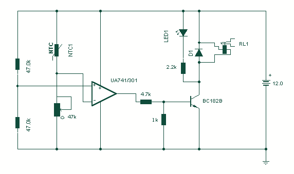
Using a thermistor in the position shown makes a heat activated sensor. A change in temperature will alter the output of the opamp and energize the relay and light the LED. Swapping the position of the thermistor and 47k...
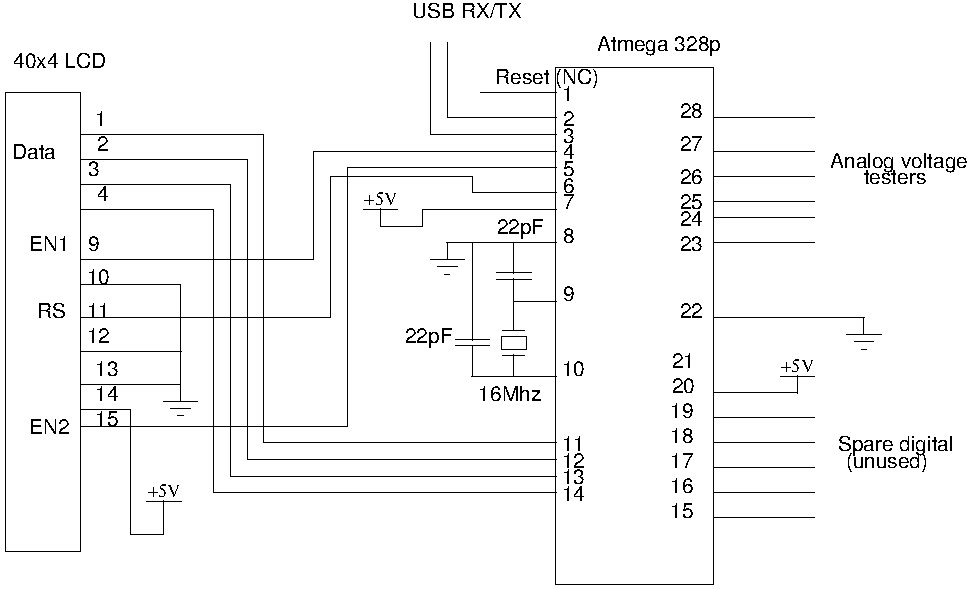
Drive a four-line LCD panel using an Arduino. The project initially aimed to control the LCD for displaying arbitrary information but evolved to include functionalities such as timekeeping, EEPROM read/write operations from the Atmel 328p, and voltage measurement. Multiple...

The Maya utilized several calendars concurrently, one of which is known as the "long count." This calendar is a continuous record of days starting from a zero date that corresponds to August 13, 3114 BC. According to the Maya...
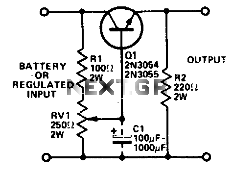
Integrated circuits (ICs) that require 3 or 6 volts can be powered from a battery or a fixed regulated supply with a higher voltage using the circuit illustrated. It is essential to mount the transistor on a heatsink, as...
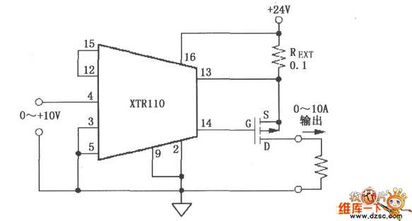
As depicted in the image, when the output current surpasses 40mA, the internal resistance of 50Ω in the XTR110 (R9) must be substituted with an external resistance, REXT. This external resistance is connected between pins 13 and 16. The...
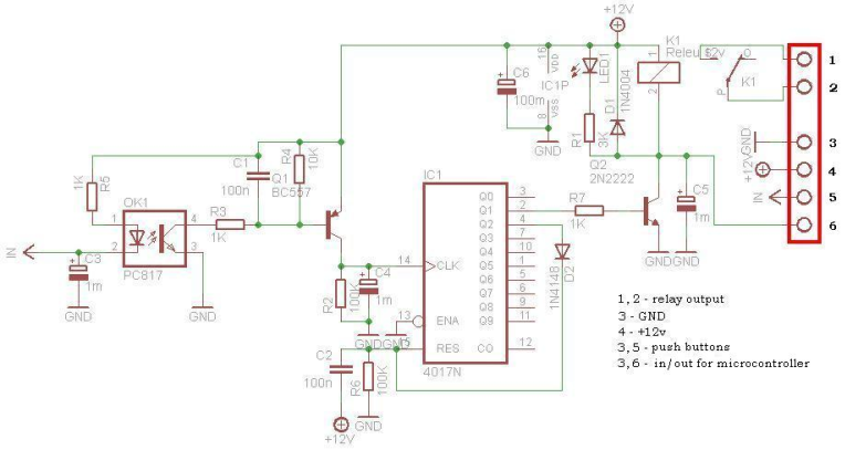
This circuit is operating the room illuminates. The basic component of the circuit is a IC1 (CD4017). Push buttons room are connected by normally wired to the circuit. All circuit is separately by optocoupler, which means that the circuit...