
cdmp3 cd with cdroom circuit diagram

The described circuit serves as a power supply for a CD-ROM drive, facilitating its use as an independent audio playback device. The power supply must deliver two voltage levels: +5V and +12V, which are standard for powering CD-ROM drives. The +5V supply typically powers the digital logic circuits within the CD-ROM, while the +12V supply is necessary for the motor that spins the disc and for other mechanical components.
To construct this circuit, a transformer or a switching power supply can be utilized to convert the mains voltage to the required output levels. A bridge rectifier can be employed to convert the AC voltage from the transformer to DC voltage, followed by filtering capacitors to smooth the output. Voltage regulators may be used to ensure stable output voltages at +5V and +12V.
The D-type power connector will be essential for interfacing the power supply with the CD-ROM drive. The pin configuration should be checked against the specifications of the CD-ROM to ensure proper connection. Additionally, implementing protection features such as fuses or thermal cutoffs can enhance the reliability and safety of the circuit.
Overall, this setup allows for a versatile audio solution, enabling users to enjoy CD audio without the need for a computer, making it suitable for various applications, including portable audio systems or integration into custom audio projects.Most of the CDROMS available have an Audio-Out Output to either plug in the headphones or connect it to an amplifier. This circuit enables one to use the CDROM as a stand alone Audio CD player without the computer. This circuit is nothing but a power supply which supplies +5v, +12V and Ground to the CDROM drive and hence can be used without the co
mputer. You should buy a D-type power connecter to connect this circuit`s outputs to the CDROM. 🔗 External reference
Related Circuits

The ADSP-2103 and ADSP-2105 are digital signal processors that interface with the AD7714. When the output is active, the ADSP-2103/2105 configuration includes the RFS non-TES non-terminal set to a low level, while the SCLK terminal is configured for serial...
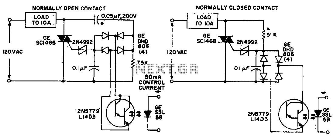
Both circuits utilize the GE SC146B, a 200 V, 10 A Triac for load current contacts. These triacs are activated by standard SBS (2N4992) trigger circuits, which are managed by a photo-Darlington configuration, functioning through the DA806 bridge as...

This battery saver circuit can automatically turn off a small piece of test equipment after a desired period of time, allowing for worry-free operation in a workshop environment. The circuit utilizes a CD4011 integrated circuit (IC) to function as...
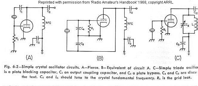
The frequency of a crystal-controlled oscillator is maintained with high precision through the use of a quartz crystal. The frequency is primarily determined by the dimensions of the crystal, particularly its thickness, while other circuit parameters have minimal impact....
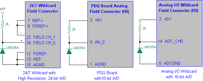
Interfacing the LM335A temperature sensor with A/D converters involves measuring temperature using the LM35 and LM335A sensors alongside the 9S12 HCS12 microcontroller. This process includes analyzing both calibrated and uncalibrated temperature errors of integrated circuit temperature sensors. The LM335A is...

This circuit comprises a 15V TOP224Y, 2A output DC switching power supply. It utilizes three integrated circuits: IC1 is a monolithic regulator (TOP224Y), IC2 is an optocoupler (NEC2501), and IC3 is a precision voltage reference (TL431). The TL431 (IC3)...