
Celestron Ultima 8 Drive Corrector Design
The Celestron Ultima 8 telescope's control system is designed to facilitate smooth tracking of celestial objects, which is critical for astrophotography and observation. The inverter circuit plays a vital role by converting the low-voltage DC power from the battery to the AC voltage required by the synchronous motor, ensuring accurate and consistent movement in right ascension. The integration of a microcontroller, specifically the PIC 16F84A, provides flexibility and programmability, allowing for precise control over motor speed and direction. The decision to incorporate a variable frequency drive enhances the system's adaptability, enabling adjustments based on specific observational needs.
The use of a transformer to manage the voltage conversion highlights the importance of selecting appropriate components to ensure reliable operation. The previous challenges with the transformer indicate that careful consideration must be given to power ratings and load requirements to maintain optimal performance. The inclusion of protective elements, such as the series diode, is essential for safeguarding the circuit against potential damage from reverse polarity, which could occur during setup or maintenance.
Overall, the design of the Ultima 8's drive system reflects a balance between functionality, reliability, and the potential for future upgrades. The thoughtful integration of various components and the provision for aftermarket enhancements underscore the system's versatility, making it suitable for both amateur and professional astronomers.The Celestron Ultima 8 is an 8-inch SCT telescope with single-axis drive. In the non-PEC variant of the Ultima, the base contains an inverter circuit used to convert 12VDC to 120VAC used by the AC synchronous motor that clocks the telescope in right ascension. A plug-in hand paddle is used to alter the frequency of the 120VAC supply to correct the motor speed during astrophotography. Provision is also made to drive an optional/aftermarket DC gearhead motor for adjustments in declination. The drive electronics in the base appear to be prone to failure. An alternative to repairing the original electronics is to remove the lead acid battery and the old drive electronics and replace them with a new and hopefully more reliable drive corrector circuit.
The new drive corrector is based upon a design presented in this paper: Alcor - A Microcontroller-Based Control Circuit for Conventional AC Telescope Drives by Michael A. Covington, which describes a variable frequency, two phase drive circuit for AC syncronous motors used in telescope clock drives.
The initial design described here is Covington`s hardware design pretty much verbatim, built into the Ultima base. The PIC 16F84A microprocessor is the heart of the design. I initially went with the same chip used in Alcor in order to avoid modifying the Alcor firmware as the hardware was debugged.
The chip could be updated to a more modern, less expensive PIC alternative. The drive corrector employs a common 120V primary, 12VCT secondary power transformer connected in reverse to convert the two-phase, low voltage signal produced by Vishay IRL 530 logic level input FET`s to a high voltage signal that approximates a sine wave. Based on measuring less than 20 mA when driving the RA motor direct from 120VAC mains (about 2W), I initially chose a 6.
0 VA transformer, the Triad FS12-500, which proved to have insufficient power to drive the motor. I replaced it with a scavenged 12. 0 VA model that worked. I am still not sure why. [Postscript: I got the original transformer working in the v2 design after adding a 1N4004 diode between the 12V and 5V supply, so the power rating was likely not the issue. ] 12VDC power is supplied to the base via a 2. 1 mm I. D. , 5. 5 mm O. D. coaxial power connector, the type of jack used in the original drive electronics, and by many other telescopes.
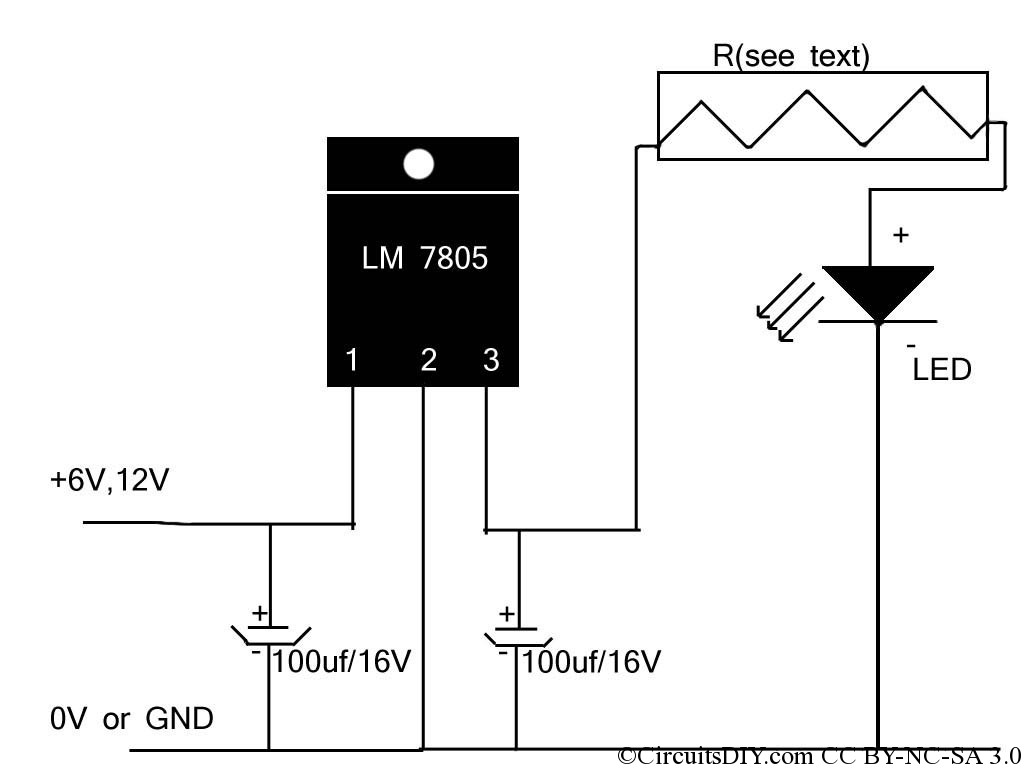
The inner conductor is the positive. Most panel-mount jacks will allow the negative outer conductor to become electrically connected to the metal base housing. This is OK provided the DEC jack is insulated from the panel housing. A series diode protects the circuit from accidental polarity reversal. The LM7805 voltage regulator converts 12VDC power to 5VDC required by the circuit. This 1A regulator is overkill for the design shown here, but given the amount of circuit board real estate left over, I thought it wise to build in some headroom for expansion.
Apparently Celestron resold the JMI Motodec with a Celstron label for this telescope. This 12VDC gearhead motor attached to the base via a 3. 5 mm TRS jack with a right-angle adapter. Since the polarity of the DEC motor is reversed depending on the direction of adjustment, the jack should be completely insulated from the metal base housing which as described above is electrically connected to the outer (negative) pole of the 12VDC power jack. 🔗 External reference
Related Circuits
The Oscillator Design Guide is integrated into Agilent EEsof's Advanced Design System environment, functioning as a smart library and interactive handbook for creating effective designs. It enables quick oscillator design, interactive characterization of components, and provides in-depth insights into...
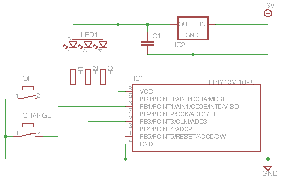
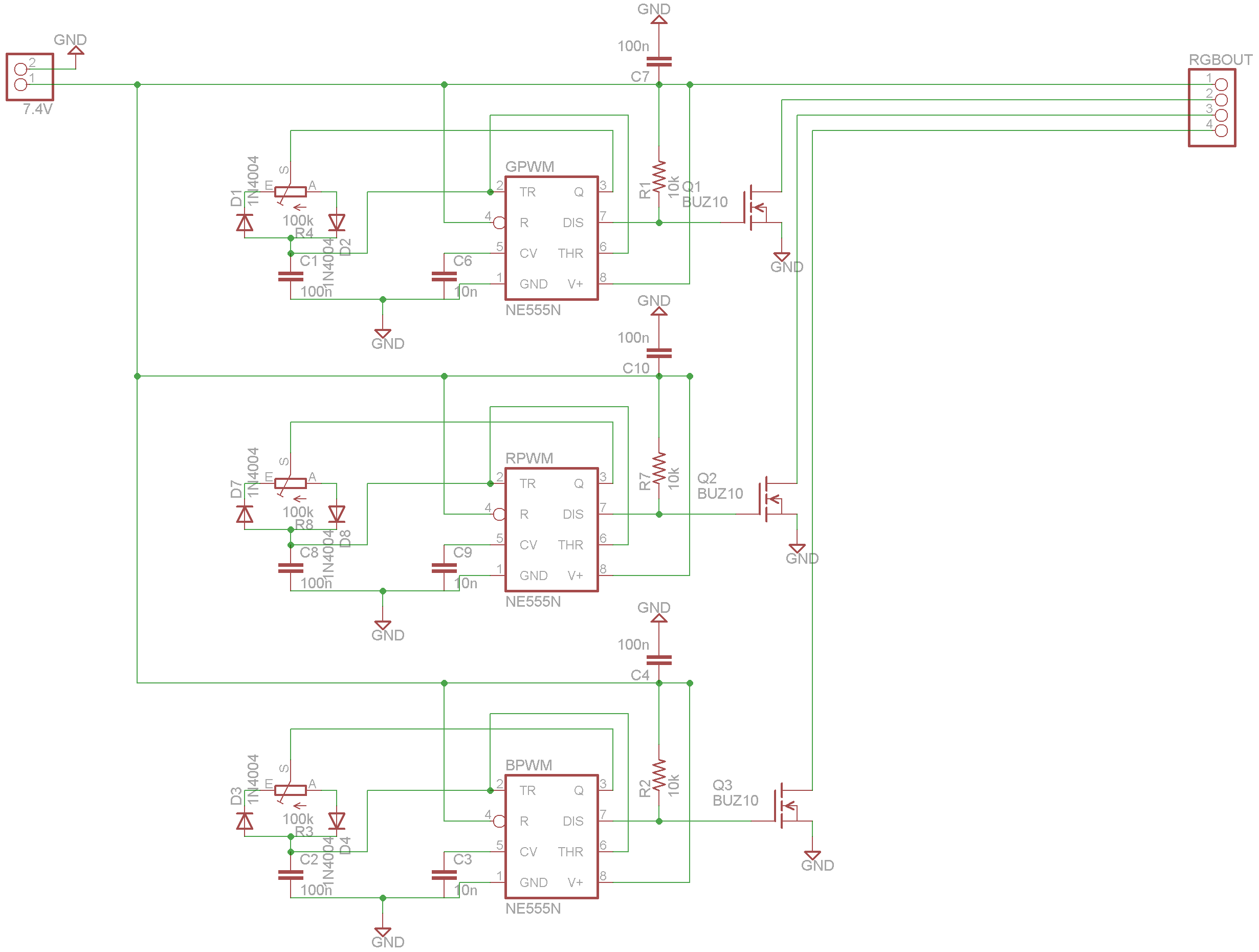
This project demonstrates the use of an ATTiny microcontroller and an RGB LED to create a light that continuously cycles through random colors, with the ability to change color dramatically at the press of a switch. The inspiration for...
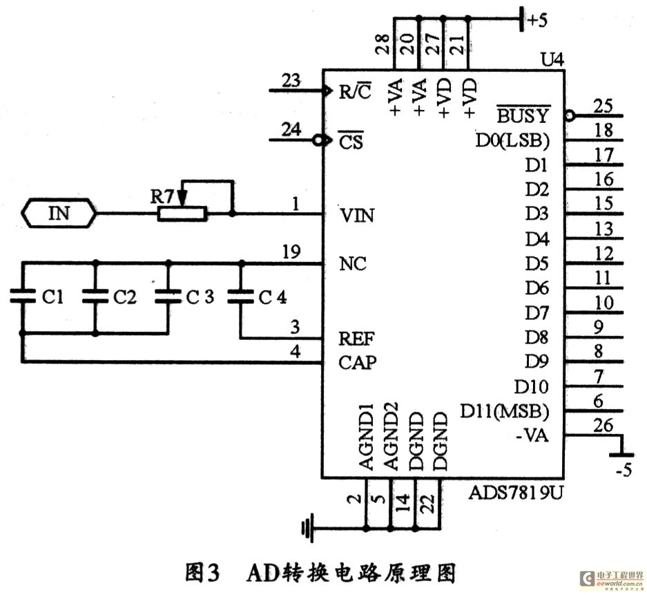
With the rapid advancement of microelectronics and technology in information systems, digital technology represented by microcontrollers is evolving continuously. Microcontrollers are characterized by their small size, low power consumption, high expandability, and convenience in control functions. They are widely...
If the reader arrived here via Google, they may have encountered other circuits for high-power LED driving that include many components such as inductors, operational amplifiers, various regulator ICs, transistor feedback networks, and microcontrollers. While those circuits tend to...

The TEA5551T monolithic integrated radio circuit can be utilized to design an AM radio receiver, intended for use as a portable radio receiver with headphones. The TEA5551T radio receiver circuit encompasses all necessary components for a complete AM receiver,...
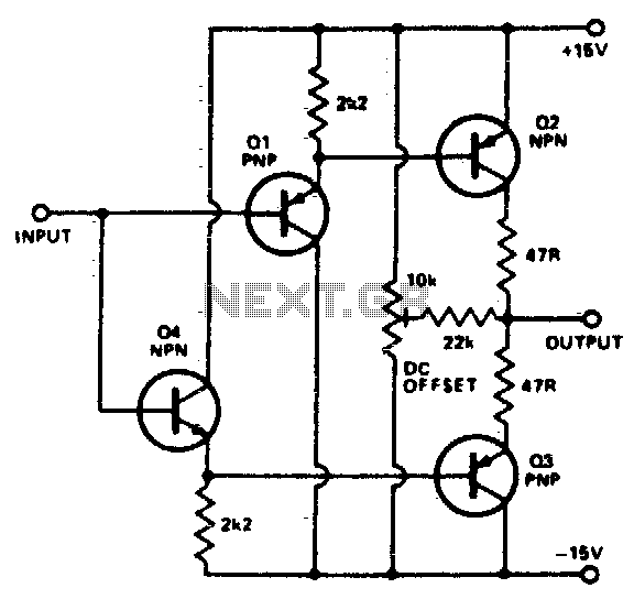
To buffer a test generator to the outside world requires an amplifier with sufficient bandwidth and power handling capability. The circuit is a very simple unity gain buffer. It has a fairly high input impedance, a 50-ohm output impedance,...