
Cheapest High power LED driver circuit diagram

The circuit described is a straightforward high-power LED driver designed for reliability and ease of assembly. The use of the LM7805 voltage regulator provides a stable output voltage of 5V, which is essential for driving high-power LEDs effectively. The forward voltage ratings of the LEDs dictate the necessary voltage drop across the current-limiting resistor, R.
In the case of the 1Watt LED, the voltage drop across the LED is approximately 3.4V. Therefore, the excess voltage that needs to be dissipated by the resistor is 1.6V (5V - 3.4V). The current flowing through the LED is 300mA, allowing for the calculation of the resistor value using Ohm's Law (V = IR). The required resistance can be calculated as follows:
R = V/I = 1.6V / 0.3A = 5.33 Ohms.
Considering standard resistor values, a 5.6 Ohm resistor is selected, which is readily available and meets the power rating requirement of 0.48 Watts. The power rating is calculated using the formula P = I²R, giving:
P = (0.3A)² * 5.33 Ohms ≈ 0.48 Watts.
For the 3Watt LED, the same approach applies. The forward voltage is again approximately 3.4V, leading to a similar calculation for the resistor value needed to limit the current to 700mA. The voltage drop across the resistor would be:
R = 1.6V / 0.7A = 2.29 Ohms.
A standard resistor value of 2.2 Ohms is suitable for this application. The power rating for this resistor is calculated as:
P = (0.7A)² * 2.2 Ohms ≈ 1.08 Watts.
Thus, a resistor rated at 2 Watts is recommended to ensure reliability and longevity in operation. This simple LED driver circuit is advantageous for applications requiring straightforward design and assembly while effectively driving high-power LEDs.If you came here through Google, then you might have seen other circuits too for high power LED driving which consists of much parts, like inductors, op-amps, different regulator IC`s, transistor feedback networks, microcontrollers etc. Those circuits are more efficient than this one but the making expense and difficulty is much more high and so
I am here showing you the simplest high power LED driver circuit. In market, we can get 1Watt and 3Watt LED easily. And the ratings of those 1Watt LEds are Forward Voltage 3. 2V 3. 6V, Forward Current 300mA and for the 3Watt ones, m the ratings are Forward Voltage: VF3. 4V, Forward Current :700mA. Here, for a fixed reference supply, LM7805 regulator I. C which can deliver upto 1Amps of current, and in our cases the max required current is 700ma or 0. 7Amps, so no problem there. And since the resistor R will be eating the extra 1. 6 volts(5. 0-3. 4). So what would be the value of R For 1 watt model, there`s current of 300mA, so the value of the resistor should be 5. 3 Ohms(appx) and wattage should be 0. 48. So a 5. 6ohms 1/2watt general purpose resistor will do the job perfectly. And similarly, for the 3Watt model, the value of R would be 2. 2Ohm 1. 25Watt(or 2Watt). 🔗 External reference
Related Circuits
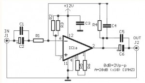
The video amplifier circuit utilizes the LM359 integrated circuit, which is a dual, high-speed, programmable current mode (Norton) amplifier. This circuit is suitable for general-purpose video amplification applications. The LM359 is designed to operate as a high-speed amplifier, making it...
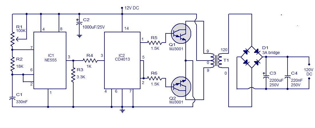
This is a simple circuit designed to convert 12V DC to 120V DC. The circuit comprises two main phases: the inverter stage and the rectifier and filter stage. The NE555 integrated circuit (IC1) is configured as an astable multivibrator,...
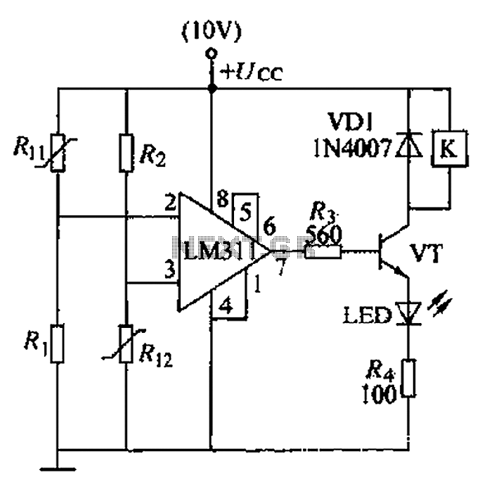
A boiler control circuit is designed to regulate the temperature of water in a hot water heating system. This circuit typically utilizes a comparator's comparison function to manage the heating equipment. The circuit includes a thermistor that forms a...
To measure the input impedance of an unknown circuit, first set the signal generator to a current source with a magnitude of 1 amp. A shunt resistor of 100 megohms is also required. This setup is beneficial for measuring...
This discussion assists in selecting the most appropriate microprocessor supervisor integrated circuit (IC) for specific applications and provides solutions for various common supervisory issues encountered with microprocessors. Microprocessor supervisor ICs are critical components in ensuring the reliable operation of microprocessor-based...
This circuit utilizes a JFET to receive signals from an LED and buffer them. The output voltage is managed using an IC 1458 or LM1458, which provides approximately 7 volts in darkness and experiences a drop of about 2...