
Cell Phone Battery Meter 3.6 Volt

For the LED voltages, three 390-ohm resistors are arranged in series with an adjustable 5K resistor at the bottom. Assuming the bottom resistor is set to 2K ohms, the total resistance sums to 390 + 390 + 390 + 2000 = 3170 ohms. The current through the resistors is derived from the reference voltage (3.9 volts) divided by the total resistance, yielding approximately 3.9 / 3170 = 1.23 mA. This results in a voltage of about 0.00123 * 2000 = 2.46 volts for the bottom LED, and approximately 0.00123 * 390 = 0.48 volts for each subsequent LED. Hence, the LEDs illuminate at voltage levels of 2.46, 2.94, 3.42, and 3.9 volts. A fully charged cell phone battery typically measures around 4.2 volts. The 5.6K resistor can be adjusted to modify the upper voltage limit, while the lower 5K resistor can be adjusted to set the lowest voltage for the bottom LED. It is important to note that a power supply of 6 to 12 volts or greater is required to operate the circuit.
This circuit operates by utilizing a TL431 voltage reference IC, which is a versatile component capable of providing precise voltage regulation. The TL431 is configured in a feedback loop with the voltage divider formed by the 10K and 5.6K resistors, ensuring stable voltage output. The adjustment terminal's constant 2.5 volts serves as a reference point for the current flowing through the resistors, allowing for accurate voltage readings across the LED bar graph.
The LED bar graph consists of four LEDs, each representing a specific voltage level. The use of three 390-ohm resistors in series helps to limit the current through the LEDs, ensuring they operate within safe limits. The adjustable 5K resistor at the bottom allows for fine-tuning of the lowest voltage threshold, providing flexibility in the circuit's operation.
The circuit's design ensures that as the battery voltage increases, more LEDs will light up, providing a clear visual indication of the battery's charge level. This is particularly useful for applications where monitoring the battery status is critical, such as in portable electronic devices. Additionally, the ability to adjust the reference voltages allows for calibration based on the specific characteristics of the battery being used.
In summary, this LED bar graph circuit effectively illustrates the state of charge of a Lithium-Ion battery, employing a TL431 voltage reference and a carefully designed resistor network to achieve accurate voltage representation across multiple LED indicators.This is a similar circuit to the above and provides a 4 LED bar graph indicating the voltage of a common 3. 6 volt Lithium - Ion recharable cell phone battery. The reference voltage is provided by a TL431 programmable voltage source which is set to 3. 9 volts where the TL431 connects to the 1K resistor. The lower reference for the LED at pin 14 is s et with the 5K adjustable resistor. The programmed voltage of the TL431 is worked out with a voltage divider (10K 5. 6K). The adjustment terminal or junction of the two resistors is always 2. 5 volts. So, if we use a 10K resistor from the adjustment terminal to ground, the resistor current will be 2. 5/10000 = 250uA. This same current flows through the upper resistor (5. 6K) and produces a voltage drop of. 00025 * 5600 = 1. 4 volts. So the shunt regulated output voltage at the cathode of the TL431 will be 2. 5 + 1. 4, or 3. 9 volts. Working out the LED voltages, there are three 390 ohm resistors in series with another adjustable (5K) resistor at the bottom. Assuming the bottom resistor is set to 2K ohms, the total resistance is 390+390+390+2000 = 3170 ohms.
So, the resistor current is the reference voltage (3. 9) divided by the total resistance, or about 3. 9/ (390 + 390 + 390 + 2000) equals 1. 23 mA. This gives us about. 00123*2000= 2. 46 volts for the bottom LED, and about. 00123*390 =. 48 volts for each step above the bottom. So, the LEDs should light at steps of 2. 46, 2. 94, 3. 42, and 3. 9. A fully charged cell phone battery is about 4. 2 volts. You can adjust the 5. 6K resistor to set the top voltage higher or lower, and adjust the lower 5K resistor to set the bottom LED for the lowest voltage. But you do need a 6 to 12 volt or greater battery to power the circuit. 🔗 External reference
Related Circuits

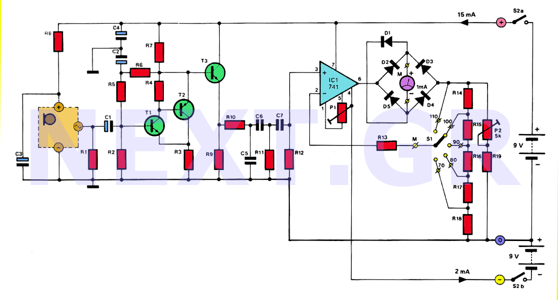
The inverting input is maintained at a low level via a 10K resistor when the circuit is powered on but not in use. During measurement activities, including calibration measurements where the input is floating, this resistor is disconnected. The...
The human ear can detect sounds ranging from 20Hz to 20KHz, with the normal range typically between 100Hz and 13KHz, depending on an individual's age and health. For accurate measurements, a range of 20Hz to 20KHz is used. Sounds...
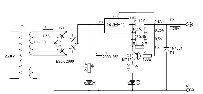
Charger for all battery types power supply. This lithium battery charger circuit is dedicated to charging lithium batteries. It uses two chips: the voltage regulator LM317T and ICL7665, which warns microprocessors of overvoltage and undervoltage conditions. Charging is completed...
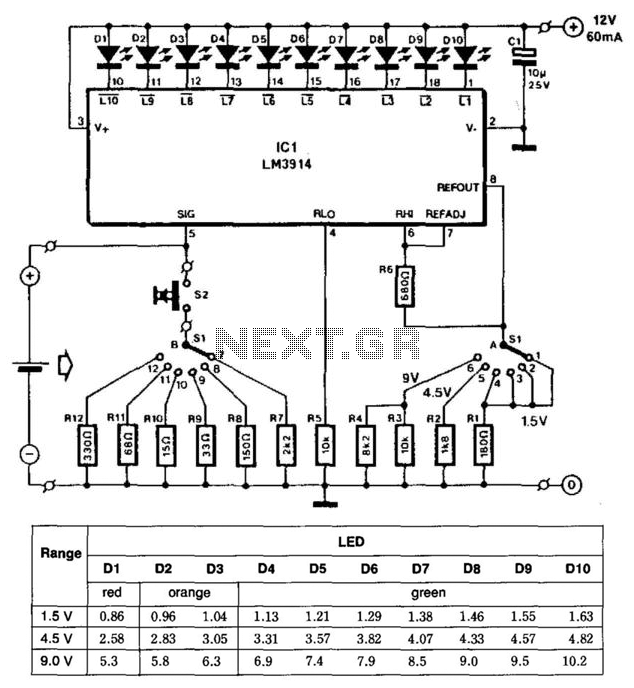
This battery tester utilizes an LM3914 bar-graph driver integrated circuit (IC). Switch SI selects the load on the battery being tested and programs the voltage range. Switch S2 applies the load to the battery under test. A table provides...
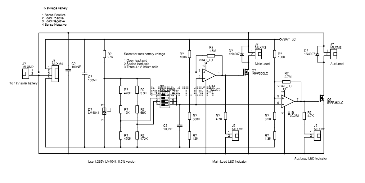
In the actual device the transistors are bolted to the aluminium case. The schematic diagram shown here represents how the circuit would be built if all components were on-board. Separate paths for load current and voltage sensing allow the...
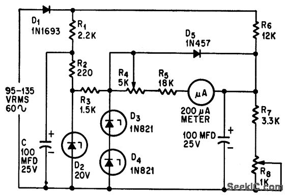
This circuit measures alternating current (AC) voltages in the range of 95 to 135 volts with an accuracy of 0.6%, utilizing a standard meter that has a 2% accuracy rating. The circuit employs Zener diodes to provide a stable...