
Cellphone-Based Device Control With Voice Acknowledgement

The described circuit is designed to enhance the convenience and efficiency of home appliance control through remote access. The microcontroller AT89C51 serves as the central processing unit, executing commands received from the cellphone interface. The DTMF decoder MT8870 plays a crucial role in interpreting the signals sent from the cellphone, converting them into a format that the microcontroller can process. The integration of voice acknowledgment via the APR9600 enhances user experience by providing immediate feedback regarding the status of the appliances.
The circuit's design incorporates various safety and operational features, such as the power-on reset circuit and manual reset switch, ensuring reliable performance. The use of discrete components, including resistors and capacitors, supports signal integrity and noise reduction, which are critical in maintaining the functionality of the DTMF decoder and the overall circuit. The configuration of input ports allows for multiple control methods, providing flexibility in appliance management.
In conclusion, this circuit exemplifies the integration of modern communication technology with traditional home appliance control, offering a user-friendly solution for managing household devices remotely. The combination of a robust microcontroller, effective DTMF decoding, and voice acknowledgment creates a comprehensive system that caters to the needs of users seeking convenience and control over their home environments.A circuit that lets you operate your home appliances like lights and water pump from your office or any other remote place. So if you forgot to switch off the lights or other appliances while going out, it helps you to turn off the appliance with your cellphone.
Your cellphone works as the remote control for your home appliances. You can c ontrol the desired appliance by pressing the corresponding key. The system also gives you voice acknowledgement of the appliance status. Fig. 1 shows the circuit for cellphone based device control with voice acknowledgement. It comprises microcontroller AT89C51, DTMF decoder MT8870, voice recording/playback device APR9600 and a few discrete components. Microcontroller AT89C51 is at the heart of the circuit. It is a low-power, high-performance, 8-bit microcontroller with 4 kB of flash programmable and erasable read-only memory (PEROM) used as on-chip program memory, 128 bytes of RAM used as internal data memory, 32 individually programmable input/output (I/O) lines divided into four 8-bit ports, two 16-bit programmable timers/counters, a five-vector two-level interrupt architecture, on-chip oscillator and clock circuitry.
A 11. 0592MHz crystal (XTAL1) is used to provide basic clock frequency for the microcontroller. Capacitor C3 and resistor R3 form the power-on reset circuit, while push-to-on switch S20 is used for manual reset. Port pins P1. 0 through P1. 7 of the microcontroller are configured to get the input from push-to-on switches S1 through S8. Pins of Port P1 are pulled high via resistor network RNW1. Port pins P2. 0 through P2. 4 are configured to receive the decoded DTMF signal from DTMF receiver MT8870. The functions of the corresponding switches (S1 through S8) and cellphone keys are shown in Table I. The DTMF decoder is used for decoding the mobile signal. It gets DTMF tone from the mobile headset`s speaker pins and decodes it into 4-bit digital signal. The DTMF decoder is operated with a 3. 579MHz crystal (XTAL2 ) In DTMF receiver MT8870 (IC3), capacitor C12 is used to filter the noise and resistors R6 and R7 help to amplify the input signal using the internal amplifier.
Pin 16 of IC3 connected to resistor R5 provides the early steering output. It goes high immediately when the digital algorithm detects a valid tone pair (signal condition). Any momentary loss of signal condition causes ESt to return to low state. Pin 17 of IC3 connected to capacitor C11 is bidirectional, acting as steering input/guard time output (St/GT). A steering logic VTSt detected at St causes the device to register the detected tone pair. The guard time output resets the external steering time constant, and its state is a function of ESt and the voltage at St.
Port P3 pins P3. 6 and P3. 7 of IC1 are configured to select the control source for the devices. These are connected to DIP switches S17 and S18 and pulled high via resistors R2 and R1, respectively. Here, we are using two control sources, switches and mobile`s key. DIP switches S17 and S18 select the control sources as shown in Table II. Pin 2. 5 of Port P2 is configured to show the rest status. That is, if none of the control sources is selected by DIP switches S17 and S18, LED1 glows. Resistor R14 limits the current through LED1. Voice acknowledgement is provided by the APR9600 (IC2). It is a single-chip voice recording and playback device that can record and play multiple messages at random or in sequential mode for 60 seconds.
The user can select sample rates with corresponding quality recording lengths. Microphone amplifier, automatic gain control (AGC) circuits, internal anti aliasing filter, internal output amplifier and message management are some of the features of the APR9600. Here the APR9600 is configured in random-access mode, which supports two, four and eight messages of fixed durations.
The length of each message is the total recording length available divided by 🔗 External reference
Related Circuits
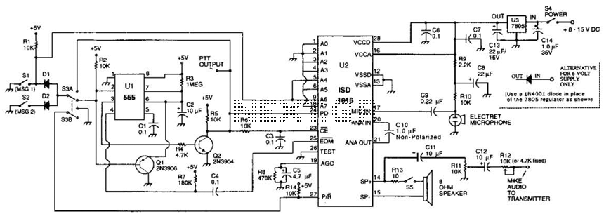
The circuit utilizes an ISD1016 audio record/playback chip from Information Storage Devices, Inc. to record and playback messages on demand. While it is primarily designed for use with transmitters, it can also serve as an electronic notepad or similar...
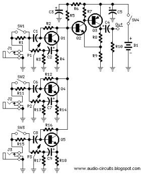
The following circuit illustrates a Mini Audio Mixer with Level Control Circuits. Features include switchable high/low sensitivity, providing high performance. The Mini Audio Mixer circuit is designed to facilitate the mixing of multiple audio signals while allowing for level control...
The automatic sprinkler controller circuit consists of a power supply circuit and a humidity measurement and control circuit, as illustrated in the accompanying figure. The power supply circuit includes a power transformer (T), rectifier diodes (VD1 to VD4), filter...

The adjustment control for the contrast of an LC-Display is typically a 10-kilohm potentiometer. This functions adequately as long as the power supply voltage remains constant. However, in cases where the power supply is not stable (such as with...
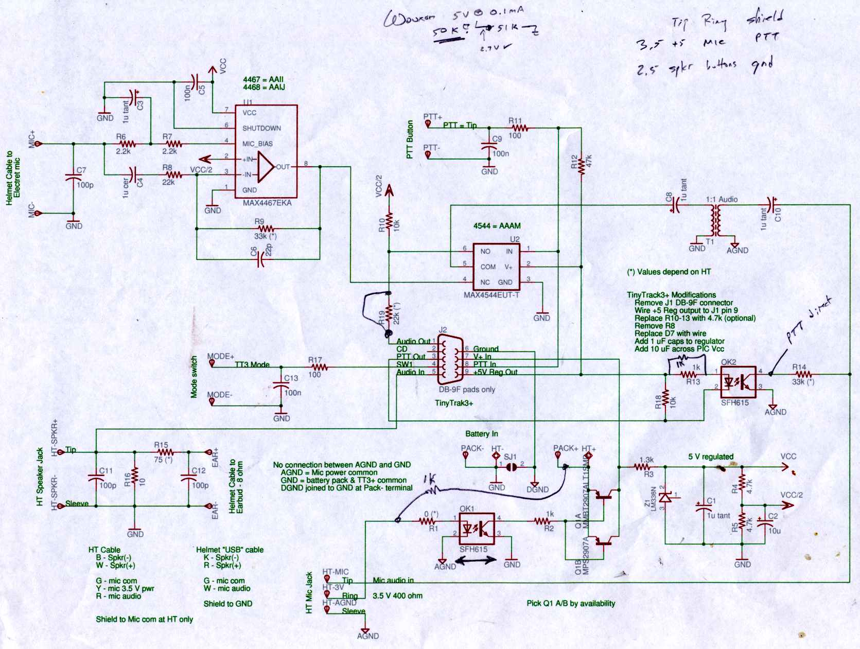
Connect the Byonics TinyTrak 3+ GPS modem, helmet earbud/mic, and external battery pack to the Z-1A, which is incompatible with the Wouxun. The KG-UV3D utilizes the Kenwood HT interface with a single ground for mic, speaker, and PTT functions,...
A simple circuit diagram illustrates a schematic for a remote control system, which consists of two parts: the transmitter and the receiver. The transmitter circuit is controlled by an NE555 integrated circuit (IC) and operates by detecting the emitted...