
Mini Audio Mixer With Level Control Circuits

The Mini Audio Mixer circuit is designed to facilitate the mixing of multiple audio signals while allowing for level control of each input. The circuit typically consists of several input channels, each equipped with a potentiometer for adjusting the gain or level of the audio signal. The switchable high/low sensitivity feature enables the user to adapt the mixer to different input signal levels, accommodating both low-level microphone signals and higher-level line signals without distortion.
The circuit can be constructed using operational amplifiers (op-amps) for each channel, which act as summing amplifiers. The output from each channel is fed into a final summing stage, where the mixed signal is generated. The use of resistors in conjunction with the potentiometers allows for precise control over the audio levels, ensuring that the output maintains a balanced mix.
Additional features may include a master volume control, which adjusts the overall output level of the mixer, and possibly an equalizer section to modify the tonal quality of the mixed audio. Power supply considerations are also crucial, with the circuit typically requiring a dual power supply for optimal performance of the op-amps.
Overall, the Mini Audio Mixer with Level Control Circuits is a versatile tool for audio applications, suitable for use in live sound environments, home studios, or any scenario where multiple audio sources need to be combined and controlled effectively.The following circuit shows about Mini Audio Mixer With Level Control Circuits. Features: with switchable high/low sensitivity, providing high .. 🔗 External reference
Related Circuits
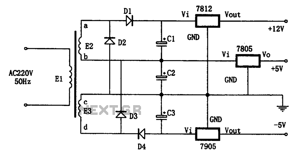
The circuit illustrated in the figure represents a specialized power supply configuration. It is straightforward in design and can be constructed using two identical secondary windings to generate three distinct DC voltage outputs: +5V, -5V, and +12V. The circuit...
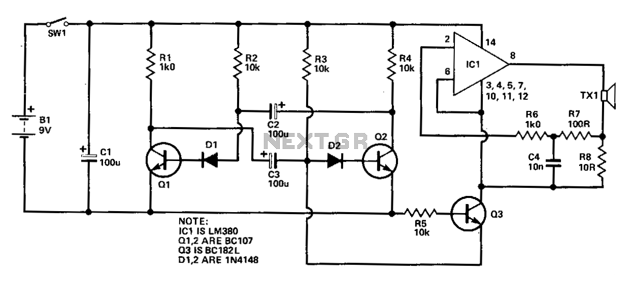
This circuit comprises two fundamental components: an oscillator tuned to 40 kHz and a voltage doubler with a pulse generator. The pulses generated are approximately 10 ms in duration and occur 2-3 times per second to minimize battery consumption...
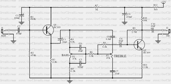
Based on the classic Baxendall tone control circuit, this provides a maximum cut and boost of around 10dB at 10KHz and 50Hz. As the controls are passive, the first transistor, Q1, is configured as common-collector to act as a...

The circuit consumes minimal current, with the battery's shelf life being the limiting factor. The only current drawn is due to the leakage of the transistor. The circuit is designed as a water level alarm but can be adapted...

This design circuit for audio amplifiers with DC coupling to the load is not commonly used today, despite its clear advantages. One advantage is the elimination of the need for a second (symmetric) power supply, and another is the...
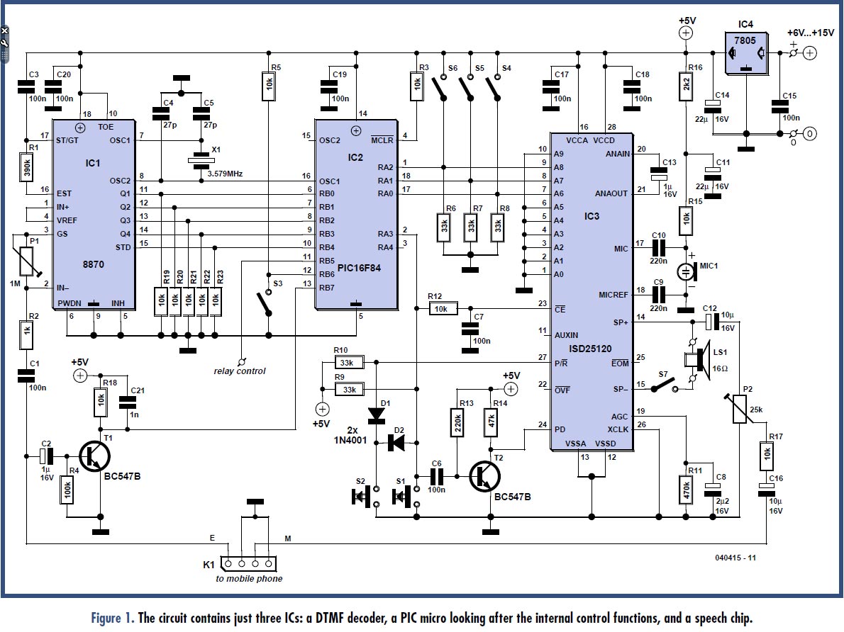
Many individuals may have an old mobile phone that is no longer in use. The circuit presented in this article repurposes the old mobile, allowing it to control an electrical appliance in or around the home by switching it...