
Contrast Control for LCDs

The circuit utilizes the LM334 integrated circuit as a constant current source, which is pivotal in maintaining a stable contrast level for the LC-Display. The primary advantage of using the LM334 is its ability to provide a constant output current that is largely independent of supply voltage variations, thus enhancing the operational reliability of the display under fluctuating power conditions. The design involves connecting the LM334 in a configuration that allows for the adjustment of the output current through a resistor (R1), which is calculated based on the desired current and the ambient temperature.
The formula for R1, R1 = 227 x 10^-6 x T / I, indicates that the resistance value is directly influenced by the temperature in Kelvin and the desired output current. This relationship is crucial in applications where temperature fluctuations can occur, as it allows the circuit to adapt accordingly. The choice of a 2.2-kilohm potentiometer for R1 enables the user to fine-tune the current output to match specific display requirements, ensuring optimal contrast without the need for constant manual adjustments.
In addition to its application with traditional LCDs, the circuit's compatibility with advanced display technologies such as OLED and PLED makes it versatile. However, it is essential to conduct preliminary tests with these newer technologies to evaluate the circuit's performance in terms of brightness adjustment, as the electrical characteristics may differ from those of standard LCDs.
Overall, this circuit design not only enhances energy efficiency but also simplifies user experience by eliminating the need for frequent contrast adjustments, making it particularly suitable for battery-operated devices where power conservation is critical.The adjustment control for the contrast of an LC-Display is typically a 10-k potentiometer. This works fine, provided that the power supply voltage is constant. If this is not the case (for example, with a battery power supply) then the potentiometer has to be repeatedly adjusted. Very awkward, in other words. The circuit described here offers a s olution for this problem. The aforementioned potentiometer is intended to maintain a constant current from the contrast connection (usually pin 3 or Vo) to ground. A popular green display with 2x16 characters supplies` about 200 µA. At a power supply voltage of 5 V there is also an additional current of 500 µA in the potentiometer itself.
Not very energy efficient either. Now there is an IC, the LM334, which, with the aid of one resistor, can be made into a constant current source. The circuit presented here ensures that there is a current of 200 µA to ground, independent of the power supply voltage.
By substituting a 2. 2-k potentiometer for R1, the current can be adjusted as desired. Circuit diagram:The value of R1 can be calculated as follows: R1 = 227x10-6 x T / I. Where T is the temperature in Kelvin and I is the current in ampG¨res. In our case this results in: Note that the current supplied by the LM334 depends on the temperature. This is also true for the current from the display, but it is not strictly necessary to have a linear relationship between these two. Temperature variations of up to 10 ° will not be a problem however. This circuit results in a power saving of over 25% with an LCD that itself draws a current of 1. 2 mA. In a battery powered application this is definitely worth the effort! In addition, the contrast does not need to be adjusted as the battery voltage reduces. When used with LCDs with new technologies such as OLED and PLED it is advisable to carefully test the circuit first to determine if it can be used to adjust the brightness.
The value of R1 can be calculated as follows: R1 = 227x10-6 x T / I. Where T is the temperature in Kelvin and I is the current in ampG¨res. In our case this results in: The current supplied by the LM334 depends on the temperature. This is also true for the current from the display, but it is not strictly necessary to have a linear relationship between these two. Temperature variations of up to 10 ° will not be a problem however. This circuit results in a power saving of over 25% with an LCD that itself draws a current of 1. 2 mA. In a battery powered application this is definitely worth the effort! In addition, the contrast does not need to be adjusted as the battery voltage reduces. When used with LCDs with new technologies such as OLED and PLED it is advisable to carefully test the circuit first to determine if it can be used to adjust the brightness.
🔗 External reference
Related Circuits
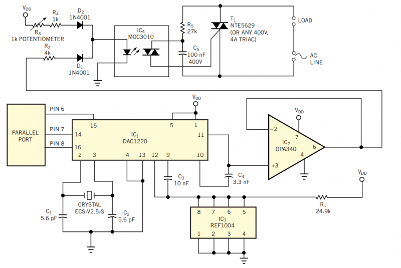
Using the simple circuit in Figure 1, you can control the light intensity in your room or work area from your PC. The heart of the circuit is a low-power D/A converter that converts digital words from a computer's...
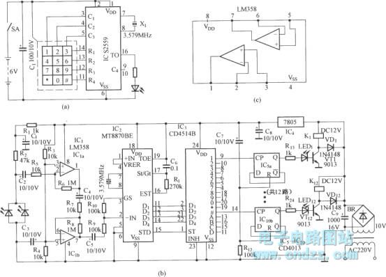
Figure (a) illustrates an infrared emission circuit composed of a 12-key keyboard and an S2559. Figure (b) displays a DTMF decoder circuit along with a channel control circuit utilizing the MT8870. Figure (c) presents a voltage amplifier circuit constructed...
In certain industries, a computer-controlled 4-20 mA current loop is utilized to manage various equipment. This current loop is employed to transmit a signal over a distance. The 4-20 mA current loop is a standard method for transmitting analog signals...
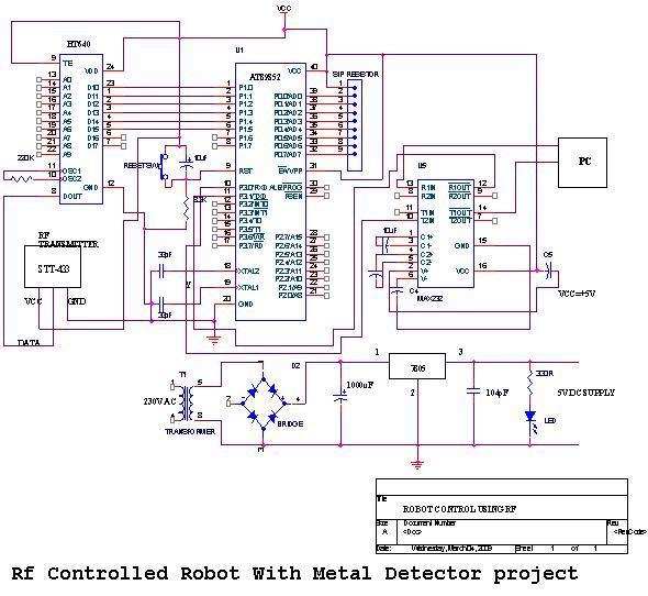
An embedded C-based RF-controlled robot equipped with a metal detector, along with wireless image and voice transmission capabilities. This project report is intended for electronics and communication engineering students. The project involves the design and implementation of an RF-controlled robot...
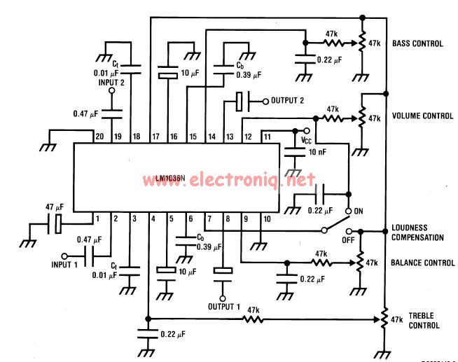
This volume controller equalizer electronic project is designed using the LM1036 DC tone volume controller, featuring a volume and balance circuit for stereo applications. The four control inputs of the LM1036 volume controller enable the control of bass, treble,...
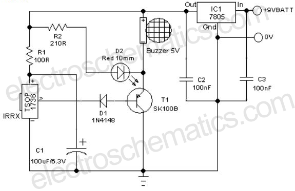
A remote-controlled alarm circuit utilizing the TSOP1736 is designed for easy use by elderly individuals or patients confined to bed. This battery-operated alarm system eliminates the need for routing electric cables to a calling bell switch, making it a...