
cellphone operated land rover

The mobile-operated land rover project exemplifies a practical application of robotics and communication technology, integrating hardware and software seamlessly. The use of the ATmega16 microcontroller provides a robust platform for processing input signals and controlling motor functions through the L293D motor driver. The DTMF decoder MT8870 plays a crucial role in interpreting user commands, converting audio tones into actionable binary signals that the microcontroller can understand. This project not only reinforces theoretical concepts learned in the classroom but also enhances problem-solving skills by addressing real-world challenges through innovative design and implementation. The entire system is designed to be user-friendly, allowing for straightforward operation via standard mobile phones, which broadens accessibility and usability for users unfamiliar with complex robotics systems. The project serves as an excellent educational tool, demonstrating the integration of communication systems, microcontroller programming, and motor control in a cohesive robotic application.I know the general rule of world that reading makes man ready, writing makes man everyday but practice makes man perfect. Only theoretical knowledge is not enough for an E. C (Electronics and communication engineering)student. A project is one of the subjects in which we have to develop hardware with software, where we not theoretically analyze t
he system but also design software and implement the same into the IC. The final phase is to test the functionally of project action. From this subject student can get opportunity of real implementation of theoretically concept of robotics and software in atmega 16 in the practical filed. Here programing, system testing and quality checking and control This documentation the report of mobile operated land rover from this documentation we can understand the hardware and software engineering concept can be implemented to a real problem.
In this project, the robot is controlled by a mobile phone that makes a call to the mobile phone attached to the robot. In the course of a call, if any button is pressed, a tone corresponding to the button pressed is heard at the other end of the call.
This tone is called DTMF (dual-tone-multiple-frequency). The robot perceives this DTMF tone with the help of the phone stacked in the robot. The received tone is processed by the (ATmega16) microcontroller with then help of DTMF decoderMT887o. The decoder decodes the DTMF tone into its equivalent binary digit and this binary number is sent to the microcontroller.
The microcontroller is programmed to take a decision for any given input and outputs its decision to motor drivers in order to drive the motors in forward direction or backward direction or turn. The mobile phone that makes a call to mobile phone stacked in the robot act as a remote. so this robotic project es not require the construction of receiver and transmitter units. The important components of this robot are a DTMF decoder, microcontroller and motor driver. An MT8870 series DTMF decoder is used here. All types of the MT8870 series use digital counting techniques to detect and decode all the 16 DTMF tone pairs into a 4-bit code output.
The built-in dial tone rejection circuit eliminates the need of pre-filtering. when the input signal given at pin 2(IN-) in single-ended input configuration is recognized to be effective, the correct-bit decode signal of the DTMF tone is transferred to (pin11) through (pin14) outputs. The pin11 to pin14 of DTMF decoder are connected to the pins of microcontroller (pa0 to pa3). The ATmega16 is a low power, 8-bit CMOS microcontroller based on the AVR enhanced RISC architecture. it provides the following features: 16kb of in-system programmable flash program memory with read-while-write capabilities, 512 bytes of eeprom, 1kb SRAM, 32(IO) lines.
outputs from port pins PD0 through PD3 and PD7 of the microcontroller are fed to the inputsIN1 through IN4 and enable pins (EN1 and EN2) of motor driver L293D IC, respectively to drive two geared dc motors. Switch S1 is used for manual reset. The microcontroller output is not sufficient to drive the dc motors, so Current drivers are required for motor rotation.
The L293D is a quad, high-current, half-h driver designed to provide bidirectional drive currents of upto600mA at voltages from 4. 5V to 36V. It makes it easier to drive the dc motors. The L293D consists of four drivers. Pins IN1 through IN4 and OUT1 through OUT4 are the input and output pins respectively, of driver 1 through driver 4.
Drivers 1 and 2, and driver 3 and 4 are enabled by enable pin 1(EN1) and pin 9 (EN2), respectively. When enable input EN1 (pin1) is high, drivers 1 and 2 are enabled and the outputs corresponding to their inputs are active. In order to control the robot, you need to make a call to the cell phone attached to the robot (through headphone) from any phone, which sends DTMF tunes on pressing the numeric buttons.
The cell phone in the robotics kept in `auto answer` mode. ( if the mobile does not have the auto answering facility, receive the call by `OK`key on the rover connected mobile and then made it in hands-free mode. ) so after a ring, the cellphone accepts the call. Now you may press any button on your mobile to perform actions as listed in the table. The DTMF tones thus produced are received by the cellphone in the robot. These tones are fed to the circuit by headset of the cellphone. 🔗 External reference
Related Circuits
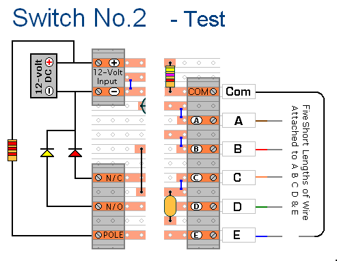
The prototype of Keypad Switch No. 2 was constructed using only the stripboard layout as a reference. If the layout has been accurately reproduced, a functional circuit will result. Once the layout is confirmed to be correct and a...
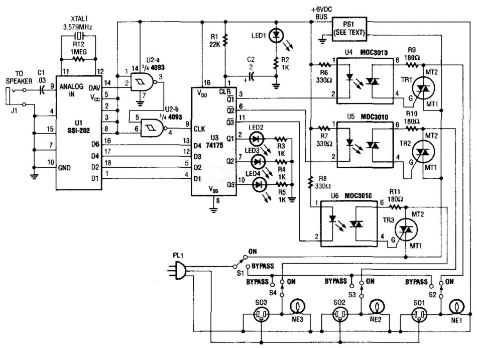
Tones from the DTMF on the telephone line are detected by U1. When a valid tone is received, pin 14 (D More: AV) of U1 produces a positive pulse that is used to drive NAND gates U2A and U2B,...

This project was developed during a Bachelor of Engineering course to enable remote control of lights and other appliances within a room. The objective was to address the common issue of forgetting to turn off devices such as fans...
The project involves using a Nokia 2300 mobile phone and its original earphones. The earphones function correctly for radio listening and phone conversations. However, the MT8870 integrated circuit does not provide output when connected to the AT89S52 microcontroller. A...
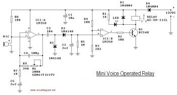
This circuit diagram illustrates a voice-operated relay, which functions similarly to a sound-activated switch circuit. It activates and deactivates the switch based on sound input. The output switch of this circuit is controlled by a relay. The release time...
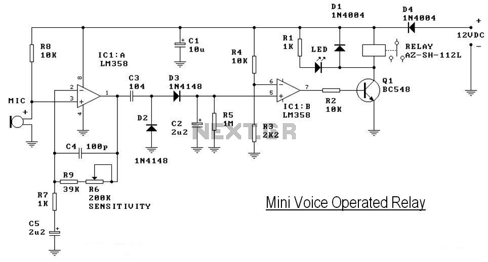
This circuit diagram represents a voice-operated relay. It functions similarly to a sound-activated switch circuit, which toggles the switch on and off (connects and disconnects) based on sound input. The output switch of this circuit is AC. The voice-operated relay...