
cf led lamp

The proposed circuit design incorporates a bridge rectifier, typically composed of four diodes arranged in a specific configuration to convert AC voltage to DC voltage. The AC mains voltage is first fed into the bridge rectifier, which allows current to flow in both directions, effectively converting the alternating current into a unidirectional current suitable for LEDs. The RC circuit is integrated to limit the current flowing to the LEDs, ensuring that they operate within their safe current ratings.
The capacitor in the RC circuit is responsible for storing energy and releasing it in a controlled manner, while the resistor serves to limit the maximum current that can flow through the circuit. The values of the resistor and capacitor can be adjusted based on the specific requirements of the LED load, ensuring optimal performance and longevity of the LEDs.
In practical applications, careful consideration must be given to the selection of components, particularly the bridge rectifier diodes, which must be rated for the maximum expected current and voltage. Additionally, the resistor must be chosen to limit the current to a level that is safe for the LEDs while still providing adequate brightness.
Thermal management should also be addressed, as components may generate heat during operation. Adequate ventilation or heat sinking may be necessary to prevent overheating, especially in compact enclosures.
Overall, this approach offers a practical and efficient solution for creating LED lighting powered directly from AC mains, utilizing recycled materials and simple circuitry to achieve effective illumination.Make LED lighting that is powered directly from the AC mains (120-Volt AC), due to the lack of having any inexpensive AND safe enclosures for the circuitry. While I was gathering some old failed CFLs one day with the intention to recycle them, I realized that the body of CFLs (aka the ballast cases) would be about the right size for holding the circuitry needed to make some compact 120-Volt LED
lamps. In addition, the CFL bodies are designed to be both fire-retardant and safe for use with AC mains power; thus making them a safer alternative to cheap "project" boxes. Though, the best attribute of reusing a CFL ballast case is that you get the standard edison screw base connector for easy interfacing to most existing light fixtures.
In order to reuse the CFL`s ballast case, the case needs to be separated from the fluorescent tube (which is usually a spiral shape. Most CFLs are constructed with a joint line between the bottom of the fluorescent tube and the top of the ballast case.
This joint between the two plastic parts of the case is usually epoxied together, so the best way to separate it is to cut through the seam. I`ve found that the best way to open this joint is to use a hacksaw to cut all the way around the CFL until the plastic seam is completely cut open*.
Once the seam is open, the fluorescent tube will only be connected to the ballast case by 2 or 4 very thin, uninsulated wires. These wires can easily be cut with a knife or wire cutters*. See My TCP EDO-9 CFL teardown page for more photos of the teardown process. * USE CAUTION WHEN HANDLING THE CFL to ensure that you don`t shatter or crack the fluorescent tube. Most fluorescent tubes contain trace amounts of mercury and must be recycled or otherwise disposed of properly!
After you`ve separated the ballast case from the fluorescent tube, you can usually remove the ballast from the ballast case by gently prying up one corner of the printed circuit board. The ballast board will be connected to the edison screw base connector by two short wires. The goal is to cut these wires as close as possible to the circuit board, so the ballast can be removed but also so that as much of the wire remains in the empty ballast case as possible.
Since LEDs are low-current devices, they generally cannot be directly powered from 120-Volt (mains) power without a power supply or current-limiter of some sort. For the design of this compact LED lamp, I opted to use a simple RC circuit and bridge rectifier as a buffer between the LEDs and the mains power.
The simple circuit behaves like a current-limited power source for the LEDs, and I chose it due to it`s extreme simplicity. Below is the schematic of this circuit and a SPICE simulation of it`s input and output behavior. This circuit relies on capacitive energy transfer, and thus only works correctly from AC power at 50-60Hz.
The resistor limits the peak inrush current to a safe value for the LEDs, while the bridge rectifier diodes allow power to be delivered to the LEDs during both the positive and negative half-cycles of the AC waveform. Thus, the LEDs shine with a nice, relatively constant light (unlike many LED christmas light sets which produce a very noticeable flashing/"strobing" effect due to the lack of a full bridge rectifier).
I built the power supply circuit on solderless "breadboard" and tested its real world performace with 7 green LEDs connected to it; while powered from the AC mains power. The simple power supply works well, producing about 30mA peak, which is about the maximum continuous forward current for the "super bright" green LEDs I chose to use.
By the way, use breadboards as shown at YOUR OWN RISK with AC mains voltages! They are NOT designed or rated for use with high-voltages like used in this project! With that said, I`ve experienced no problems using them with AC mains voltages for sh 🔗 External reference
Related Circuits
Capacitors C1 and C2, in conjunction with a speed controller, function by receiving voltage at the gate of the MOSFET. When the voltage on C is applied, it activates the operation of the MOSFET. In this circuit configuration, capacitors C1...

A programmable clock timer circuit that utilizes individual LEDs to indicate hours and minutes. Twelve LEDs can be arranged in a circle to represent the twelve hours of a clock face, while an additional twelve LEDs can be arranged...
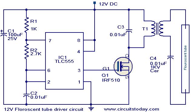
This circuit provides a simple and effective method for driving fluorescent lamps using a 12 V power supply. The circuit consists of an oscillator, a MOSFET switch, and a step-up transformer to power the fluorescent lamp. The TLC 555...
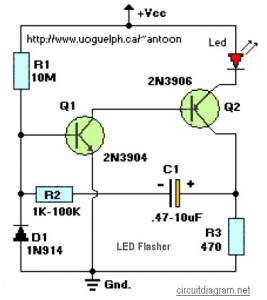
This circuit is designed to flash a high-brightness red LED (5000 mcd), making it suitable for use in fake car alarms or other devices intended to attract attention. The specific values of the components are not critical, allowing for...
For several years, a rear fog lamp has been mandatory for trailers and caravans to enhance visibility in foggy conditions. When the fog lamp is activated, the fog lamp of the towing vehicle must be turned off to prevent...
The lifespan of a lamp can be prolonged by enhancing the conditions under which its filament operates. This involves eliminating the inrush overcurrent surge and reducing the mechanical stress (vibration) on the filament caused by an AC source. The...