
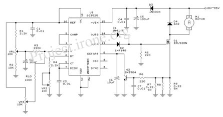
lamp flasher circuit with mosfet irf511

In this circuit configuration, capacitors C1 and C2 play a crucial role in managing the gate voltage of the MOSFET, which is essential for controlling its switching behavior. The speed controller modulates the voltage supplied to the gate, allowing for precise control over the MOSFET's operation. When the voltage across capacitor C reaches a specific threshold, it triggers the MOSFET to turn on, enabling current to flow through the load connected to the MOSFET.
The design typically involves a feedback mechanism where the speed controller continuously monitors the output speed of the motor or device being controlled. Adjustments to the gate voltage are made based on the feedback received, ensuring that the MOSFET operates efficiently and responds to changes in load conditions.
Capacitors C1 and C2 are selected based on their capacitance values, which affect the time constant of the charging and discharging cycles. This time constant is critical for determining the responsiveness of the MOSFET to changes in the gate voltage, thus influencing the overall performance of the speed control system. Proper selection of these components is vital for achieving the desired dynamic response and stability in the circuit.
The MOSFET itself is chosen based on its voltage and current ratings, ensuring it can handle the load requirements without overheating or failing. Additionally, the gate resistor may be included to limit the inrush current to the gate, protecting the MOSFET from potential damage during operation.
Overall, this configuration exemplifies a common approach in electronic speed control applications, utilizing the properties of capacitors and MOSFETs to achieve efficient and effective motor control.C1 and C2 with a speed controller works by receiving the voltage at the gate of the MOSFET when the voltage on C turn ON the other would be to drive MOSFET operation. 🔗 External reference
Related Circuits
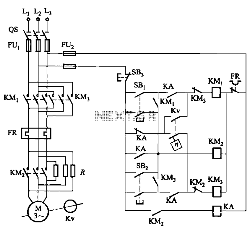
The circuit shown in Figure 3-129 is the C650-2 lathe brake control circuit, utilizing a speed control relay. The C650-2 lathe brake control circuit is designed to manage the braking mechanism of a lathe machine effectively. This circuit incorporates a...
This is an audio power amplifier that delivers 40 W at 8 ohms in Class A operation. The power transistors are continuously active, enabling a substantial current to flow. The audio power amplifier described operates in Class A mode, which...

A passive high-pass filter has been added after the output of the operational amplifier (op-amp) to eliminate DC offset, with the op-amp powered by +12V and the negative supply at 0V. A feedback resistor (Rf) of 500K Ohms is...
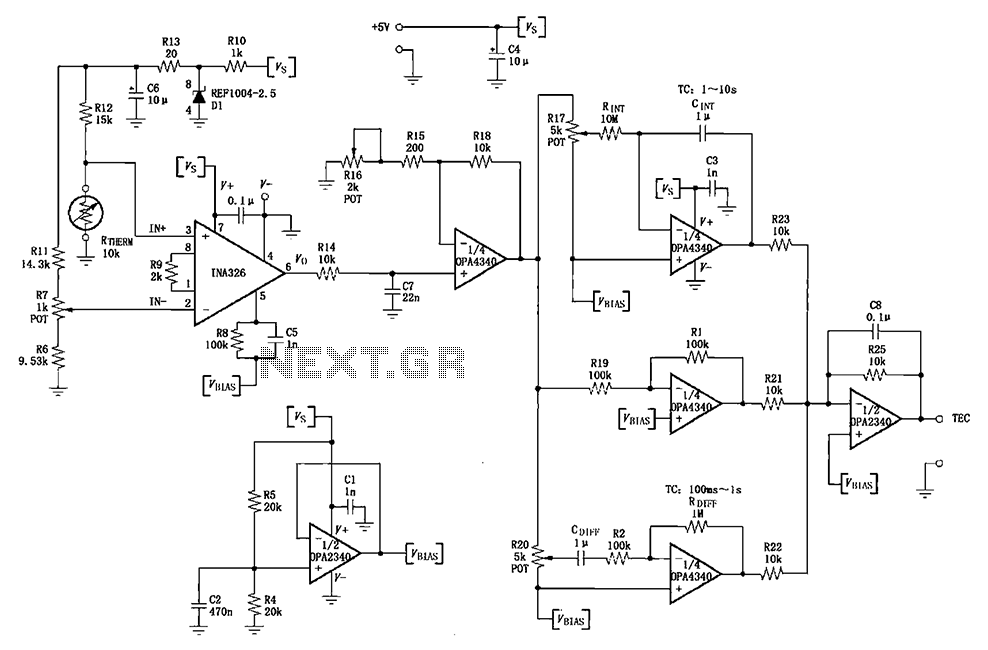
The INA326/327 forms a single power PID (proportional-integral-derivative) controller as illustrated in the temperature control loop. This circuit is primarily designed for temperature measurement and control. A thermistor, designated as RTHERM, detects temperature changes and converts them into an...
This article explains the principle of the Audison LR604XR amplifier. The principle is straightforward; it is recommended to combine the text with a careful reading of the complete schematic. To fully understand this principle, it is advisable to review...
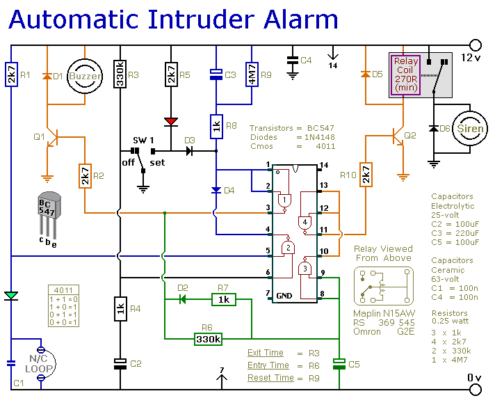
This is a simple single-zone burglar alarm circuit. Its features include automatic exit and entry delays and a timed bell/siren cut-off. It is designed to be used with the usual types of normally-closed input devices such as magnetic reed...