
Multipurpose Circuit for telephone

This multipurpose circuit serves as an enhancement for standard telephone systems by providing both audio and visual indications of the on-hook status. The circuit is designed to be connected in parallel with the existing telephone instrument, allowing it to operate without interfering with the normal functionality of the telephone.
The core components of the circuit include a microcontroller, which monitors the telephone line's status, and an LED indicator that visually signals when the telephone is on-hook. Additionally, a small speaker or buzzer can be incorporated to provide an audible alert, enhancing the user experience by ensuring that the on-hook status is easily recognizable.
The circuit operates by detecting the voltage levels on the telephone line. When the phone is on-hook, the voltage remains at a standard level, which the microcontroller identifies. Upon detection of this condition, the microcontroller activates the LED indicator and the audio alert, thus providing a clear indication to the user.
Power for the circuit can be derived directly from the telephone line, ensuring that no external power source is required. This feature enhances the convenience and portability of the circuit. The design should also include appropriate resistors and capacitors to filter any noise and stabilize the operation of the microcontroller.
In summary, this multipurpose circuit not only adds functionality to existing telephone systems but also improves user awareness of the device's status through effective audio-visual cues. It is a valuable addition for users who require enhanced notification features in their telecommunication devices.Multipurpose Circuit for telephone. This add-on device for telephones can be connected in parallel to the telephone instrument. The circuit provides audio-visual indication of on-hook,. 🔗 External reference
Related Circuits

This RF converter converts amateur TV signals in the 420 to 450 MHz region to VHF channel 3 or 4, allowing reception of those signals on a standard TV receiver. RF amplifier Q1 feeds mixer M1, and Q3 acts...

This circuit is designed for the ignition of a direct current (DC) fluorescent lamp rated between 6 to 8 watts. It utilizes a common pole-blocking oscillator that consists of a transistor (VT) and is induced by the secondary side...

Figure A, B, and C illustrate the test rod end clip, with a positive power supply terminating test equipment. The B and C ends are connected in series with the load, where C represents the negative side of the...

This post presents an interesting topic about switching power supply circuit diagrams for those who wish to learn more. A switching power supply is a type of power supply that uses a switching regulator to convert electrical power efficiently. Unlike...
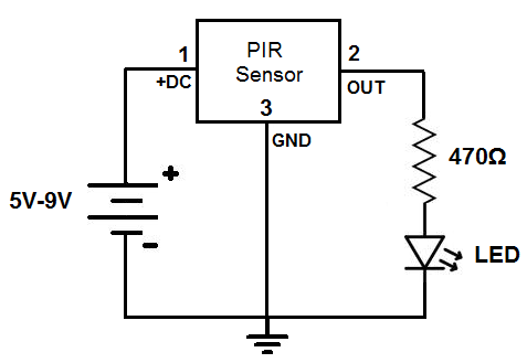
This circuit is designed to detect motion or movement, with its most common application being the detection of a person moving through an area covered by the motion detector. The primary electronic component utilized for this detection is the...

For several years, a rear fog lamp has been mandatory for trailers and caravans to enhance visibility in foggy conditions. When the fog lamp is activated, the fog lamp of the towing vehicle must be turned off to prevent...